


www.desatech.com
115121-01B16
5. Rotate control door up into control com-
partment and slide on end into side of
compartment.
6. Tilt out one end rst then pull remaining
door assembly through opening.
7. Replace door, by starting with door upside
down, pins up and facing unit. Follow step
5 in reverse until pins are rmly set back
in notches and door will close.
8. Replace discharge deector and magnet
assemblies.
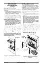
SERVICING CONTROL PANEL
The control panel can be serviced from inside
the unit by removing rear control cover on in-
side of rebox. Follow steps 2 through 4 under
Optional Heater Accessory, page 10.
If control assembly needs complete replace-
ment, proceed to remove the entire control
assembly as follows:
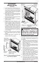
1. Remove the glass doors (if equipped).
Follow instructions under Optional Glass
Doors, page 8.
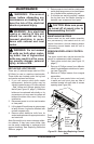
2. Remove each retaining screw holding
screen rods and pull entire screen and
rod assembly out from locating hole on
inside top edge of replace (see Figure
18, page 9).
3. Remove log bed from hearth pan and
place in a safe area. Log bed is attached
with contact magnets only. This step is
included to keep logs from being damaged
during panel replacement.
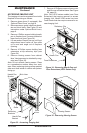
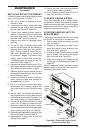
4. Remove 2 Phillips screws holding control
cover to control panel inside rebox (see
Figure 21, page 11).
5. Slide control cover to the right and swing
out locking tabs from notched openings
on top. See detail Figure 21, page 11.
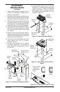
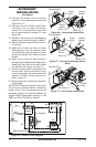
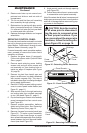
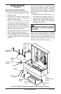
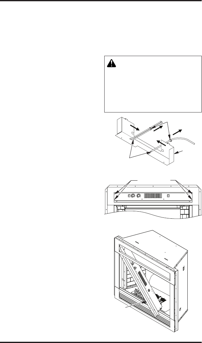
6. Pop out bushings on control cover and slip
power harnesses free from control cover
(see Figure 30).
7. Remove magnet assemblies, deector
shield and control door. See Removing/
Replacing Control Door, page 15.
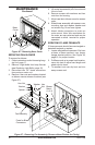
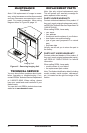
8. Remove 4 screws from control panel (see
Figure 31). Tilt entire control assembly
forward to clear lower ange at upper
door rail and slide assembly down through
space between the front face and rebox
mount (see detail Figure 32).
9. Angle control panel out through opening
(see Figure 32).
10. Follow these instructions in reverse order
to reassemble control panel assembly.
Note: Be certain that all wires, harnesses and
bushings are returned to their normal position
and free of damage before reconnecting sup-
ply power to the replace.
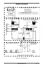
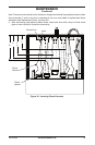
CAUTION: Note the location
of all wires prior to disconnect-
ing. Be sure to reconnect wires
to their proper locations. If you
are unsure about the proper wire
locations, follow the wiring dia-
gram Figure 28, on page 14.
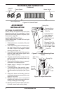
MAINTENANCE
Continued
Figure 30 - Detaching Power Harnesses
LOWLOW
MAIN
POWER
FLAME SPEED FLAME BRIGHTNESS
HEATER
Panel Screws
Figure 31 - Panel Screws Location
Figure 32 - Removing Control Panel
Control
Panel
Power
Harnesses
Bushings
Control
Cover