


10 USSC
All electrical connections should be done by a
qualied electrician.
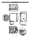
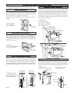
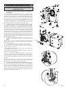
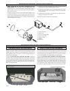
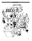
1. To replace the Honeywell Limit Control (A): Unplug from
power supply
The control may be removable thru the access panel on item
“B”. However it may be easier to remove item “B” entirely for bet-
ter access. Remove item “B” by means of the eight(8) screws. If
siliconed, use a utility knife to score the silicone along the edges
of the part. Take off the cover of the control (A), remove the
three wires, and continue to remove the control by means of the
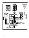
two screws retaining it. Use the wiring diagram in the rear of this
manual to re-connect the new control. Reattach item “B” and
re-silicone all the seams with weather resistant silicone.
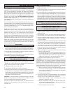
2. To remove the return air box (D): Unplug from power supply.
If siliconed, use a utility knife to score the silicone along the edges
of the part. Remove item “B” as described above. Then remove
the four(4) screws down each side and the four(4) across the top
of the return air box. Pull the box back away from the unit enough
that you can reach in to remove the snap-in plug (C) from the
top of the box. The power supply cord will need to be feed back
thru the plug in the bottom of the air box for complete removal.
When re-attaching, make sure that the three plugs in the top of
the Fan Center (G) are properly plugged in. Do not forget to put
the snap-in plug (C) back in place. Re-silicone all the seams with
weather resistant silicone.
3. To remove the Distribution Blower (E): Unplug from power
supply.
Remove items”B” and “D” as described above. Unplug the blow-
er from the top of the Fan Center (G). Remove the four(4) screws
retaining the blower.
4. To remove the Blower Motor: Unplug from power supply.
Perform number 3 above. Before removing the motor from the
housing, measure two things:
1.) The distance from the edge of the motor to the edge of the
motor bracket. Record (d1) _________________
2.) The distance of the shaft remaining outside the coupling on
the blower wheel. Record (d2) __________________
These two measurements dictate the position of the blower in-
side the housing and is critical in determining motor longevity.
Repositioning of the blower motor, bracket, and wheel in respect
to one another should keep as close to the factory position as
possible.
Remove the three(3) screws (I) from the blower housing. Then
loosen the bolt (J) on the motor shaft. Next, loosen or remove the
bolt (K) in the motor bracket to remove the motor.
5.
To remove the Blower Capacitor (F): Unplug from power supply.
This may be accomplished by working thru the 12 inch diameter
return duct hole in the Return Box. Otherwise, you must remove
items”B” and “D” as described above. Unplug the blower from
the top of the Fan Center (G). Using pliers with rubber coated
handles, unplug the two connections on the capacitor. Remove
the two screws and cap bracket.
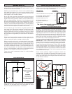
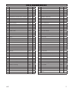
DISTRIBUTION BLOWER & ACC.
A
C
B
D
C
F
E
H
G
J
I
d1
d2
K