


2319 Laurelbrook Street, Raleigh, NC 27604 · (800) 542-7221 · FAX (919) 834-4526 · www.ultimate-products.com
-
11
-
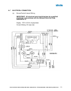
A. 7 ELECTRICAL CONNECTION (CONT.)
The electrical supply to the heater is by three wires: live, neutral and ground
connections. It is recommended that the supply cable be in metallic conduit to
the 3/4'” hole provided.
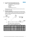
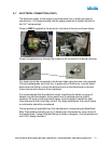
Power is ONLY supplied to the terminal in the back of burner as shown below:
Power is supplied to fan through the knock out on the side of the burner housing.
Fan leads should be connected to the burner leads using the wire nuts provided.
Connect yellow/green wire from fan, to green wire of the burner, connect either
black wire from the fan, one to the white and one to the black/brown of burner.
Insure that conduit clamp is firmly tightened.
It is recommended that the electrical circuit controlling the heater or group of
heaters include thermostats, a time switch and if required manual control
switches. All such controls and switch gear must be rated to handle the total
inductive load of the circuit they control. For large installations, the use of relays
or contractors should be considered.
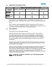
Control panels are available from the manufacturer incorporating multiple Black
Bulb Thermostats controlling up to 10 heaters per thermostat for zone control of
the heated area. Typical External Wiring is shown in diagram. (Control panels are
not A.G.A. design certified.)