


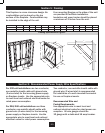
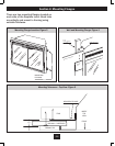
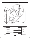
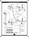
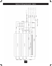


Framing Specications: Figure 1
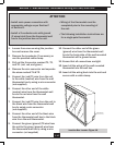
This replace is a zero clearance design. No
combustibles can be placed on the top
surface of the replace. Combustibles may
be installed to the edge of the unit.
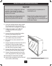
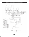
For 120 volt installations use two conductor,
non-metallic sheath cable with ground wire
(3 wires total) for the incoming power supply
on replace inserts. Use the appropriate wire
to meet local and national electrical codes for
rated power consumption.
For 208/240 volt installations use three
conductor, non-metallic sheath cable with
ground wire (4 wires total) for the incoming
power supply on replace inserts. Use the
appropriate wire to meet local and national
electrical codes for rated power consumption.
MODEL A B C D E F G H I J K L M
33EB304AAS 15.0” 33.0” 29” 28.5” 23.0” 32.8” 29.6” 18.25” 23.6” 14.3” 48.0” 28.0” 28.0”
33EB364GRS 16.0” 39.0” 33” 32.7” 27.2” 38.7” 36.0” 22.0” 27.6” 15.3” 55.0” 34.0” 34.0”
D
E
F
G
H
I
J
L
K
M
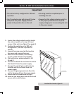
Four mounting anges on the sides of the unit
are provided to facilitate installation.
Insulation and vapor barrier should be placed
a minimum of 2 inches from the unit.
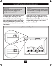
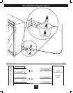
Two conductor, non-metallic sheath cable with
ground wire (3 wires total) is recommended
for installation of a wall mounted thermostat
for use on replace inserts.
Recommended Wire and
Fusing Requirements
Use appropriate wire to meet local and
national electrical codes for rated power con-
sumption. All wire gauges should be
12 gauge with a dedicated 15 amp breaker.
Section 2: Recommended Power Supply Wire Specications
Section 1: Framing
E-3