


LISTINGS AND CODE APPROVALS
THE BUILDERS BOX SERIES HAS BEEN TESTED AND APPROVED IN ACCORDANCE WITH THE
CSA xxxxxxx No.xxxxxxx STANDARDS FOR FIXED AND LOCATION
DEDICATED ELECTRIC ROOM HEATERS.
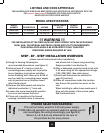
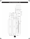
MODEL SPECIFICATIONS
MODEL
NUMBER DESCRIPTION VOLTAGE
RATED POWER
WATTS
REMOTE
CONTROL AMPS
33EB304AAS 33” STANDARD 120/208/240 1440/2100/2700 YES 12.00/10.10/11.25
39EB364AAS 39” STANDARD 120/208/240 1440/2100/2700 YES 12.00/10.10/11.25
!!! WARNING !!!
THE INSTALLATION OF THE FIREPLACE UNIT MUST COMPLY WITH THE APPLICABLE
LOCAL AND/ OR NATIONAL ELECTRICAL CODES AND UTILITY REQUIREMENTS.
THIS INSTALLATION SHOULD BE ENTRUSTED TO DULY QUALIFIED
PERSONNEL WHERE REQUIRED BY LAW.
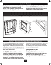
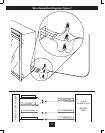
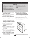
!POWER SELECTION WARNING!
This unit is factory wired for 110 volt power supply.
If 208/240 volt operation is required, slide the voltage switch
and recongure the wiring accordingly (see gure 2).
Wires L1, L2, N & G are attached to the rear of
the junction box for easy access.
! !
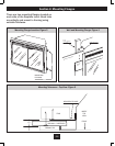
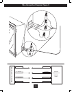
1) Rough in framing following the
recommended dimensions. (see gure 1)
2) Allow at least 8” of service cable for
connecting power supply wire to junction
box on replace insert when installing
before nishing wall. Allow up to 4 feet of
service cable for connecting power supply
wire to junction box on replace insert
after nishing wall.
3) Remove the outer jacket and strip the
individual conductors ½” from end.
4) Loosen the screw securing the junction
box cover and remove the cover.
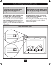
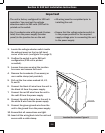
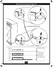
5) Place unit in position in the framed
opening, level with shims if necessary
and attach unit to frame using mounting
anges provided ( see Section 3).
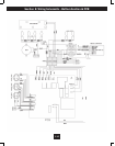
6) Wire a dedicated, properly fused circuit with
a 15 amp rating for the appropriate voltage
(120, 208/240). (See table above)
7) Install wall thermostat as outlined on
page 10 section E
8) Place all connections inside the junction
box. Secure the junction box cover on the
unit.
When installing a cable clamp make sure it
grips only the jacket of the service cable
and thermostat wire.
STEP - BY - STEP INSTALLATION OVERVIEW
(please read all instructions before installation)
E-2