


2
TABLE OF CONTENTS
Page
I. Specifications.............................................................................................................................. 3
II. Preparation For Installation....................................................................................................... 3
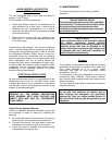
New Unit Inspection................................................................................................................... 3
Operation.................................................................................................................................... 3
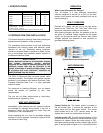
Ducting Application ................................................................................................................... 4
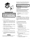
III. Installation ................................................................................................................................. 4
Liquid Aerosol ........................................................................................................................... 5
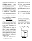
Electrical.................................................................................................................................... 5
IV. Maintenance.............................................................................................................................. 5
Cleaning..................................................................................................................................... 5
Inspections ................................................................................................................................ 6
V. Replacement Parts .................................................................................................................... 6
VI. Warranty.................................................................................................................................... 6
VII. Troubleshooting Guide......................................................................................................... 6-8
VIII. Diagrams / Exploded View Figures
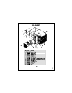
Figure 1 – T5200 Unit Assembly.................................................................................................... 9
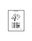
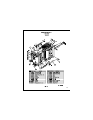
Figure 2 – T5200 Enclosure Assembly ....................................................................................... 10
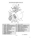
Figure 3 – T5200 Blower Motor Assembly (2HP and 3HP)......................................................... 11
Figure 4 – T5200 Blower Motor Assembly (5HP)........................................................................ 12
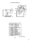
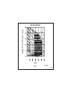
Figure 5 – Ionizer/Collector Cell.................................................................................................. 13
Figure 6 – T5200 Blower Curve ...................................................................................................14
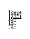
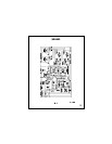
Figure 7 – Wiring Diagram........................................................................................................... 15