


3
I. SPECIFICATIONS
II. PREPARATION FOR INSTALLATION
This manual should be carefully read before starting the
preparation and installation of the air cleaner.
The installation should conform to all local ordinances
associated with building codes and electrical codes
required for the unit. Authorities having jurisdiction
should be consulted before installation is made. If there
are no local codes, the installation should conform to
the National Electrical Code.
SAFETY NOTE:
Factory designed access to all electrically charged
high voltage components contain electrical
interlocks for the safety of operating personnel. Any
additional access that may be provided in the
system, where there is access to high voltage, must
be equipped with such interlocks. Interlocks are
readily available from the factory.
The 575V, 3 Phase unit does not have internal motor
overload protection. The installer must provide overload
protection in accordance with National Electrical Code,
Canadian Electrical Code, Part 1 or other applicable
electrical codes.
For maximum air cleaning efficiency, your air cleaner
should be located as specified by your Trion
representative.
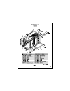
The unit can be either wall-mounted or chain-hung.
Eyebolts can be supplied by Trion.
NEW UNIT INSPECTION
Immediately, upon receiving the unit, carefully examine
the package for damage during transit. If the unit is
damaged, contact the last carrier for claim filing and
contact your Trion representative.
While unpacking the unit, look for concealed shipping
damage. If there is damage, it should be reported to the
last carrier for claim filing.
OPERATION
What is your Electronic Air Cleaner?
Your air cleaner is a high efficiency contaminant
collector designed to remove up to 95% of the dust,
smoke, liquid aerosol and other pollutants from the air
passing through it.
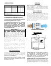
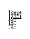
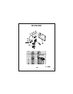
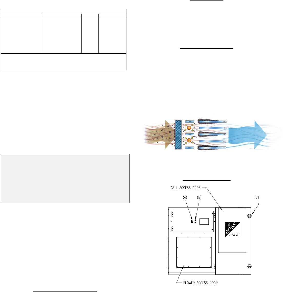
HOW IT OPERATES
Polluted air is drawn into the unit by the belt driven
blower on the T5200 unit. The T1001 and T2002 units
require an external air handler to move the air.
After passing through a pre-filter, the particles in the air
are given an electrical charge supplied by the power
supply. As the particles enter the collector cells, these
charged particles are attracted to and collected on
grounded collecting plates.
Typical Electronic Cell Operation
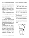
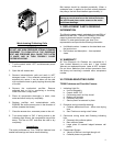
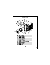
UNIT OPERATION
Control Switch (A): The control switch is located on
the cell access door. It controls the operation of the
power pack and the belt driven blower. The control
switch should be in the “OFF” position when the cell
access door is open for maintenance of the unit.
Indicating Light (B): The light located adjacent to the
control switch is an indicator of the performance of your
electronic air cleaner. When the control switch is “ON”,
the blower should operate and the indicator light should
glow. If the light does not glow or if it continually flickers
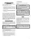
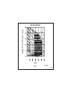
Model Voltage HP AMPS (Max)
T5200B 230V, 60 HZ, 3 PH. 2 6.8
T5200B 230V, 60 HZ, 3 PH. 3 9.7
T5200C 460V, 60 HZ, 3 PH. 2 3.4
T5200C 460V, 60 HZ, 3 PH. 3 4.9
T5200D 575V, 60 HZ, 3 PH. 2 3.2
T5200N 208V, 60 HZ, 3 PH. 2 6.8
Note:
Ionizer Voltage: 6 KVDC
Collector Voltage: 12 KVDC
Motor: (where applicable) Ball bearing, Totally enclosed, Fan Cooled.
POWER REQUIREMENTS