


TABLE OF CONTENTS
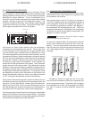
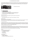
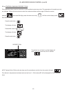
The serial tag is a permanently afxed label on which
is recorded vital electrical and refrigeration data about
your Traulsen product, as well as the model and serial
number. This tag is located in the right interior com-
partment on all Full Size Undercounter Quick Chiller
models.
I. THE SERIAL TAG
-1-
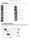
FORT WORTH, TX.
SERIAL MODEL
VOLTS Hz PH
TOTAL CURRENT AMPS
MINIMUM CIRCUIT AMPS
MAXIMUM OVERCURRENT PROTECTION AMPS
LIGHTS WATTS
HEATERS AMPS
REFRIGERANT TYPE OZ
DESIGN PRESSURE HIGH LOW
REFRIGERANT TYPE OZ
DESIGN PRESSURE HIGH LOW
370-60294-00 REV (A)
READING THE SERIAL TAG
• Serial = The permanent ID# of your Traulsen unit
• Model = The model # of your Traulsen unit
• Volts = Voltage
• Hz = Cycle
• PH = Phase
• Total Current = Maximum amp draw
• Minimum Circuit = Minimum circuit ampacity
• Lights = Light wattage
• Heaters = Heater amperage (Hot Food units only)
• Refrigerant = Refrigerant type used
• Design Pressure = High & low side operating
pressures and refrigerant charge
• Agency Labels = Designates agency listings
e-Enter The Service Access Page 8
f-Service Parameters Page 9
g-Adjusting Thermostat Set Point High Page 9
h-Adjusting Thermostat Set Point Low Page 10
i-Changing The Temperature Scale Page 10
j-Setting The 24-Hour Clock Page 11
k-Setting The Date Page 12
l-Setting Daylight Savings Time Page 12
m-Starting A Manual Defrost Page 13
n-Setting Defrost Lockouts Page 14
o-Adjusting The Door/Drawer Perimeter Heaters Page 15
p-Adjusting The Room Temperature Offset Page 15
q-Setting The Audible Alarm Style Page 16
r-Viewing Sensor Temperatures Page 16
VIII. WIRING DIAGRAM Page 17
IX. SERVICE ASSISTANCE
a-Service Information Page 18
b-Spare Parts Information Page 18
c-Warranty Registration Page 18
X. WARRANTIES Page 19
XI. SERVICE PARTS LIST Page 20
I. THE SERIAL TAG Page 1
II. RECEIPT INSPECTION Page 2
III. INSTALLATION
a-Location Page 2
b-Packaging Page 2
c-Adjusting the Casters Page 2
d-Cord & Plug Page 2
e-Power Supply Page 2
IV. QUICK CHILLER OPERATION Page 3
V. CARE & MAINTENANCE
a-Cleaning The Condenser/Filter Page 3
b-Replacing The Gaskets Page 4
c-Cleaning The Cabinet Surface Page 4
VI. DOOR Page 4
VII. MICROPROCESSOR CONTROL
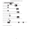
a-Control Features Page 5
b-Alarm Explanations Page 6
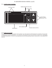
c-Control Panel Diagram Page 7
d-Notes To The User Page 7