


WSHP-SVX02A-EN 5
General
Information
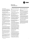
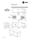
Unit Nameplate
The unit nameplate is located at the
front of the unit. It includes the unit
model number, serial number, electri-
cal characteristics, refrigerant charge,
and other pertinent unit data.
Compressor Nameplate
The nameplate for the compressors
are located on the compressor shell.
Unit Description
Before shipment, each unit is leak test-
ed, dehydrated, charged with refriger-
ant and run tested for proper control
operation.
Water-to-Refrigerant Coils
The brazed-plate water-to-refrigerant
heat exchangers for the 2-ton through
6-ton equipment are constructed of
stainless steel.
The water-to-refrigerant heat ex-
changers for the 20-ton equipment are
an inner copper tube or cupro-nickel
(option available on the source-side
only) and steel tube (tube-within-a-
tube) design.
Both heat exchanger types are leak
tested to assure there is no cross leak-
age between the water and refrigerant
gas.
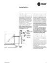
Water Connections
One inch brass swivel connections are
provided for the 2-ton through 6-ton
equipment. Each brass fitting has a
one inch gasket for the connector. The
gaskets are shipped in the electrical
compartment to prevent loss at the job
site.
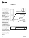
Water connections for the 20-ton are
located inside the unit at the units
front (source-side) and back (load-
side). The fitting consist of a 2-inch fe-
male pipe threaded connection.
Controls
The control system offered to control
the unit is a Basic 24 volt control for
the 2-ton through 6-ton unit sizes, and
a deluxe 24 volt micro processing
board for the 20-ton unit.
All power wiring to the equipment is
made at the unit contactor for the 2-
ton through 6-ton equipment, and at
the power block for the 20-ton equip-
ment.
All low voltage wiring is made at the
unit’s low voltage terminal board.
Wiring Connections
Troubleshooting and connection dia-
grams for the equipment may be locat-
ed in the back of this manual.
Basic 24V Controls
(for 2-ton through 6-ton units)
Safety devices for equipment contain-
ing the basic 24V control option in-
clude a low pressure switch and a
freezestat to prevent compressor op-
eration during low temperature activi-
ty. The switch is set to activate at
refrigerant pressures of 35 psig or 7
psig to fit most applications.
A high pressure switch prevents com-
pressor operation during high or ex-
cessive discharge pressures
exceeding 395 psig.
The lockout relay communicates the
low or high pressure situation to the
compressor to prevent operation. The
relay may be reset at the thermostat,
or by cycling power to the unit.
General alarm may be accomplished
through the lockout relay to drive light
emitting diodes (LEDs) on a field sup-
plied status indicating thermostat. Ter-
minal 6 on the lockout relay is open for
field use in malfunction indications.
This feature will drive dry contacts
only, and cannot be used to drive field
installed control inputs.
Deluxe 24V Controls
(for 20-ton unit)
Units containing the Deluxe 24V con-
trol design will incorporate a micro-
processor-based control board. The
Trane microprocessor board is factory
wired to a terminal strip to provide all
necessary terminals for field connec-
tion. The deluxe board is equipped
with a random start relay, anti-short
cycle timer, brown out protection,
compressor disable, unit safety con-
trol, diagnostics and a generic relay
(which may be available for field use).
See page 17 for diagnostic informa-
tion.
Desuperheater
(Option for 2-ton through 6-ton units)
For units containing the desuperheat-
er option, the unit is shipped from the
factory with a desuperheater water
coil and pump mounted internal to the
unit cabinetry. For domestic hot water
hook-up instructions, see manual
WSHPC-IN-4 or 72-9006-02.
The desuperheater pump fuse is locat-
ed in the control box within a contain-
er. The fuse is not factory installed to
avoid possible pump damage at initial
start-up. If the fuse in installed and the
unit is started without water in the sys-
tem, the pump will be damaged. See
page 17 for fuse installation.
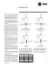
Schrader Connections
Connections for the low and high side
of the refrigeration system are located
conveniently on the unit’s right side
for the 2-ton through 6-ton units, and
behind the front, refrigeration access
panel for the 20-ton unit.