


12 WSHP-SVX02A-EN
Cleaning and Flushing
the Water Loop
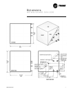
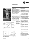
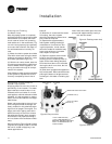
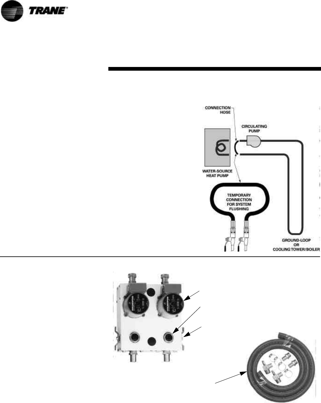
After the piping system is complete,
the flexible hose connectors should be
doubled back to complete the water
circuit external to the unit (avoiding
trash settle-out in the condenser). Fig-
ure 4. An extra pipe may be necessary
to connect the hose kits. See Page 14
for antifreeze/water mixture by vol-
ume.
(1) Water circulation system should be
filled with clean water using the water
make up connections. Note: Air vents
should be opened during filling.
(2) With the air vents closed, start the
circulating pump and then crack the air
vents to bleed off the trapped air, as-
suring circulation through all compo-
nents of the system.
Note: Make up water must be available
to the system to replace the volume
formerly occupied by the air that is
bled off.
(3) With the air vented and the water
circulating, the entire system
should be checked for leaks with re-
pairs made as required.
(4) Operate the supplementary
heat system making checks per
manufacturer’s instructions. Dur-
ing this operation, visual checks
should be made for leaks that may
have occurred due to increased
heat. Repair as required.
(5) Open the system at the lowest
point for the initial blow down
(making sure the make up water is
equal to the water being dumped).
Continue blow down until the water
leaving the drain runs clear, but not
less than 2 hours.
(6) Shut down pumps and supplemen-
tary heat system. Reconnect the hoses
placing the water-to-refrigerant heat
exchanger in the water circulating sys-
tem.
Note: Vents should be open when the
pumps and supplementary heat sys-
tem are shut down.
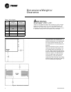
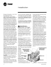
Installation
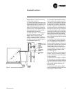
SHUT-OFF 3-WAY
PURGING CAP (2)
BRONZE OR CAST IRON PUMP
FROM UNIT’S
W.O.
TO UNIT’S
W.I.
Figure 5 Pump module
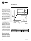
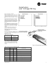
Figure 6: Hose kit
1" MPT x BARB FITTINGS,
1" MPT x BARB ELBOWS with
PRESSURE TEMPERATURE PORTS,
AND 10’ OF RUBBER HOSE with
4 HOSE CLAMPS.
VALVE (2)
Connecting a Loop Pump Kit
Closed Loop System
All piping external to the unit is the re-
sponsibility of the installer. The water
pipe installation must be done in ac-
cordance with local codes. If no local
code applies, national codes should be
followed. It is the contractor’s respon-
sibility to know and adhere to all appli-
cable codes.
Water inlet and outlet to the unit’s wa-
ter-to-refrigerant heat exchanger are
clearly marked on the submittal draw-
ings found on pages 7 through 9. The
supply and return piping must be in-
stalled correctly to the unit to ensure
the safety devices will work properly.
Units that are not piped accordingly
will not obtain the manufacturers war-
ranty.
A pump module (Figure 5) and hose kit
(Figure 6) are typically used to connect
the unit to closed loop piping in do-
mestic applications.
Figure 4: Flushing water loop