18 WSHP-SVX02A-EN
Changing Freezestat or Low Pres-
sure Cutout Switches
(WPWD/GSWD models ONLY)
Each unit has two factory installed low
pressure cutout switches and one
freezestat. Only one of the low pres-
sure cutout switches is connected to
the 24 volt control circuit, dependent
on which freezestat is being used (i.e.
35°F or 20°F). Both the freezestat and
the low pressure cutout are in the lock-
out relay circuit. The freezestat moni-
tors the temperature of the water
leaving the source and load side wa-
ter-to-refrigerant heat exchangers,
protecting the heat exchanger from
fluid freeze up. The low pressure cut-
out monitors the suction pressure of
the compressor to protect the com-
pressor from liquid floodback or oper-
ating under loss of charge conditions.
Units can be ordered from the factory
with either the 35°F or 20°F freezestat
option. The 20°F freezestat is ONLY
used on closed loop systems with an-
tifreeze solution. The 35°F freezestat is
used on all other systems. The type of
freezestat on a unit can be determined
from the appropriate digit in the model
number. Digit 11 and/or 12 with a se-
lection of 1 is a 35°F freezestat, where-
as selection 2 is a 20°F freezestat.
What Freezestat Should Be
Applied?
As previously mentioned, every unit is
shipped from the factory with two low
pressure cutouts installed in the refrig-
erant circuit. One of the low pressure
cutouts disables the compressor at 35
psig, while the other disables the com-
pressor at 7 psig. The 35 psig cutout is
used with the 35°F freezestat, while
the 7 psig cutout is used with the 20°F
freezestat.
Occasionally it will be necessary to
change the freezestat in the field. Ex-
amples of when this change-out is
necessary include:
(1) A unit with a 35°F freezestat is go-
ing to be put on a closed loop system
with antifreeze. By definition, the unit
requires a 20°F freezestat.
(2) A unit with a 20°F freezestat is go-
ing to be put on an open well system
or a closed loop system with NO anti-
freeze solution. By definition, the unit
must have a 35°F freezestat installed
prior to operation.
The best time to install the freezestat/
low pressure cutout is prior to install-
ing the unit. The freezestat is easily ac-
cessible from the top service door.
WARNING
Hazardous Voltage!
Disconnect all electric power, in-
cluding remote disconnects be-
fore servicing. Follow proper
lockout/tagout procedures to en-
sure the power can not be inad-
vertently energized. Failure to
disconnect power before servic-
ing could result in death or seri-
ous injury.
Changing a Freezestat and Low
Pressure Cutout
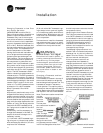
The freezestat is located in the top of
the source-side water-to-refrigerant
heat exchanger leaving water line. The
freezestat is located in the twelve
o’clock position. The capillary tube is
inserted into the well approximately 8-
inches. Remove the existing freezestat
and replace it with the new freezestat.
Note: The wires must be moved from
one low
pressure
cutout to
the other.
The low pres-
sure cutouts are located in
the insu-
lated re-
frigerant
lines. The high
pressure cutout is locat-
ed in the un-insulated
compressor dis-
charge line and is the
only pressure cutout located
in this line. Change the wires from
the old low pressure cutout to the new
low pressure cutout.
Identifying the Low Pressure Cutouts
The 7 psig low pressure cutout is used
with a 20°F freezestat. It is installed in
the insulated line and is in the piping
tee going to the external schrader port.
The 35 psig low pressure cutout is
used with a 35°F freezestat. It is in-
stalled in the insulated line and is not
connected to any fittings.
The 395 psig high press cutout is in-
stalled in the un-insulated compressor
discharge line. It is the only cutout lo-
cated in this line. Further, it is connect-
ed to an external schrader port.
If the low pressure cutout is not
changed when the freezestat is
changed, problems will occur. If the 35
psig low pressure cutout is connected
to a 20°F freezestat, the unit will go out
repeatedly on the low pressure cutout.
If the 7 psig low pressure cutout is
used with the 35°F freezestat, no prob-
lems will occur as long as the freez-
estat is operating normally. However,
if the freezestat does fail, the loop wa-
ter could freeze before the suction
pressure dropped low enough for the
7 psig cutout to take the unit off the
line. Also, in a loss of charge situation,
the heat exchanger would freeze be-
fore the freezestat could take the unit
off-line.
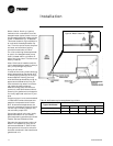
Installation
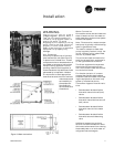
Figure 11: Pressure switch location


