


Page 7
INSTALLATION
IMPORTANT!: DO NOT LIFT THE UNIT WITHOUT TEST-
LIFTING FOR BALANCE AND RIGGING.DO NOT LIFT THE
UNIT IN WINDY CONDITIONS OR ABOVE PERSONNEL. DO
NOT LIFT THE UNIT BY ATTACHING A CLEVIS, HOOKS,
PINS OR BOLTS TO THE UNIT CASING, CASING HARD-
WARE, ANGLES, TABS OR FLANGES. FAILURE TO OB-
SERVE THESE WARNINGS MAY RESULT IN EQUIPMENT
DAMAGE.
4. When the curb and air ducts have been properly installed, the unit
is ready to be hoisted to the roof and set in position.
IMPORTANT!: “Spreader Bars” must be used when
hoisting unit.
5. IMPORTANT: The unit must be lowered into position P.V.C.
rubber tape on the curb flange permits the unit to be
repositioned if required without destroying the P.V.C. rub-
ber seals affixed to mounting curb.
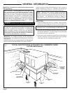
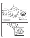
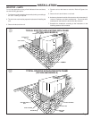
6. PLACING UNIT ON MOUNTING CURB—The unit is designed
with a perimeter drip lip that is lower than the unit base ban, see
Figure 7 insert “A”.
7. Position the unit drip lip down over and in contact with the outside
corner of the curb, as illustrated in Figure 7 insert “A”. Continue
to lower unit on top of curb, with the unit drip lip astraddle and in
contact with both the end and side rail of curb, the unit is now
resting on top of curb.
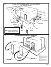
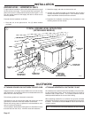
8. Take the two (2) hold down brackets shipped with curb and secure
unit to curb with hold down brackets as illustrated in Figure 8
insert “A”.
UNIT SUPPORT
If unit is to be roof mounted, check building codes for weight
distribution requirements. Refer to accessory roof curb mounting
instructions. Check unit nameplate for supply voltage required.
Determine if adequate electrical power is available. Refer to speci-
fication sheet.
LOCATION AND CLEARANCES
Installation of the unit should conform to local building codes or, in
the absence of local codes, to the ANSI/NFPA No. 70-1987 National
Electrical Code or “Latest Revision.” Canadian installations must
conform to CSA and local codes.
Select a location that will permit unobstructed airflow into the
condenser coil and away from the fan discharge and permit unob-
structed service access into the compressor compartment. Sug-
gested airflow clearances and service clearances are given in
Figure 5.
PLACING AND RIGGING
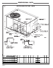
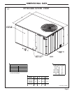
1. Before preparing the unit for lifting, check the outline drawing for
center of gravity for lifting safety. Because of placement of
internal components, the unit weight may be unevenly distrib-
uted . Approximate unit weights are given in outline drawing on
page 3.
NOTE: Accessory BAYLIFT002A Four (A) lifting lugs are recom-
mended for rigging the unit for hoisting. See Figure 7 insert “B”.
2. Insert the four lifting lugs in openings provided in drip lip on
perimeter of unit. See Figure 7 insert “B”.
3. Before hoisting the unit, be sure that the proper method of rigging
is used, with straps or slings and spreader bars for protection
during lifting.
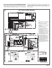
11. Access and service clearances for the unit must be given careful
consideration when locating the duct entrance openings. Fig-
ures 6 and 8 provide unit dimensions.
12. All fabricated outdoor ducts should be as short as possible.
13. Be sure the hole in the structure for the ducts is large enough to
accommodate the fabricated ducts and the insulation surrounding
them. (See Figure 6.)
CLEARANCES
1. The recommended clearances for single-unit installations are
illustrated in Figures 5 and 6. These minimum requirements are not
only an important consideration when determining unit placement,
but they are also essential to ensure adequate serviceability,
maximum capacity, and peak operating efficiency.
2. Any reduction of the unit clearances indicated in this illustration
may result in condenser coil starvation, or the recirculation of warm
condenser air. Actual clearances which appear to be inadequate
should be reviewed with a local sales engineer.
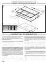
IMPORTANT!: To convert to downflow remove covers from
the downflow supply and return air openings and place them
over the horizontal supply and return air openings (painted
side out) and secure with sheet metal screws.
3. For “Roof Top Application,” unit must be elevated above roof with
a mounting Curb or Frame.
4. Exhaust vents or other sources of contaminated air should not be
near unit air inlet if outside air is to be introduced as a make-up
air or the economizer ventilation feature is to be used.
5. Check the handling facilities to insure the safety of personnel and
the unit(s).
6. CAUTION MUST BE TAKEN AT ALL TIMES TO AVOID PER-
SONAL INJURIES AND/OR DAMAGE TO EQUIPMENT.
7. The unit must be mounted level for proper drainage of defrost
water through the holes in the base pan.
8. Flexible duct connectors must be of a flame retardant material. All
duct work outside of the structure must be insulated and weath-
erproofed in accordance with local codes.
9. Roof flashing must be installed to seal the roof curb cavity and
must conform to local building codes.
10. Holes through exterior walls must be sealed in accordance with
local codes.