


Page 14
START - UP
To start the unit in the cooling mode, set the thermostat system
switch to COOL and move the thermostat COOL indicator to a
setting below room temperature. The condenser (outdoor) fan
motor compressor and evaporator (indoor) fan motor will operate
automatically.
OPERATING PRESSURES
After the unit has operated in the cooling mode for a short period of
time, install pressure gauges on the gauge ports of the discharge
and suction line valves. Check the suction and discharge pressures
and compare them to the normal operating pressures provided in
the unit's SERVICE FACTS.
NOTE: Do not use the pressures from the unit's SERVICE FACTS
to determine the unit refrigerant charge. The correct charge is
shown on the unit nameplate. To charge the system accurately,
weigh in tIhe charge according to the unit nameplate.
VOLTAGE
With the compressor operating, check the line voltage at the unit.
The voltage should be within the range shown on the unit name-
plate. If low voltage is encountered, check the size and length of the
supply line from the main disconnect to the unit. The line may be
undersized for the length of the run.
COOLING SHUT DOWN
Place the system selector in the OFF position or reset thermostat at
a setting above room temperature.
Do not de-energize the main power disconnect except when unit it
to be serviced. Power is required to keep the heat pump compres-
sor warm and boil off refrigerant in the compressor.
STARTING THE UNIT IN THE HEATING MODE
NOTE: See the section on "Sequence of Operation" for a descrip-
tion of the heat pump heating operating sequence.
Check to make sure all grilles an registers are open an all unit
access doors are closed before start-up.
Slowly set the thermostat above rom temperature until achieving a
first stage call for heat and place the fan switch in the AUTO or ON
position.
HEATING SHUT-DOWN
Place the system selector switch at OFF or place the heating
selector lever at a setting below room temperature.
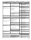
PRE-START QUICK CHECKLIST
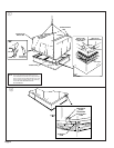
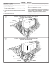
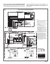
● Is the unit properly located and level with the proper clearance?
See Figure 5.
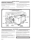
● Is the duct work correctly sized, run, taped, insulated, and
weatherproofed with proper unit arrangement. See Ductwork
Installation section.
● Is the condensate line properly sized, run, trapped, and pitched?
● Is the filter of the correct size and number? Is it clean and in place?
● Is the wiring properly sized and run according to the unit wiring
diagram?
● Are all the wiring connections, including those in the unit, tight?
● Has the unit been properly grounded and fused with the recom-
mended fuse size? See Wiring Data.
● Is the thermostat level, correctly wired, well located, and set for the
proper heat anticipation?
● Have the air conditioning systems been checked at the service
ports for charge and leak tested if necessary?
● Do the condenser fan and indoor blower turn free without rubbing,
and are they tight on the shafts?
● Has the indoor blower speed been determined and the proper
speed been set? See the Unit Wiring Diagram.
● Has all work been done in accordance with applicable local and
national codes?
● Are all covers and access panels in place to prevent air loss and
safety hazards?
STARTING THE UNIT IN THE COOLING MODE
CAUTION: Before starting the system on the cooling cycle, turn the
thermostat switch to OFF and close the unit disconnect switch. This
procedure energizes the compressor crankcase heater, vaporizing
any liquid refrigerant in the crankcase. This is a precaution against
foaming at startup which could damage the compressor bearings.
Allow the heater to operate a minimum of eight (8) hours.
NOTE: See the section on "Sequence of Operation" for a descrip-
tion of the cooling operating sequence.
▲WARNING:
DO NOT OPERATE THE UNIT
WITHOUT THE EVAPORATOR FAN ACCESS PANEL IN
PLACE. REINSTALL THE ACCESS PANEL AFTER
PERFORMING ANY MAINTENANCE PROCEDURES ON THE
FAN. OPERATING THE UNIT WITHOUT THE ACCESS
PANEL PROPERLY INSTALLED MAY RESULT IN SEVERE
PERSONAL INJURY OR DEATH.