


Page 6
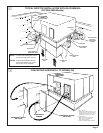
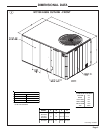
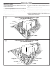
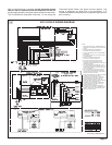
REQUIRED CLEARANCE FOR UNIT INSTALLATION
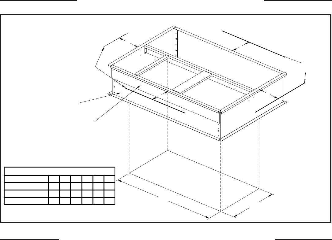
AND ROOF PENETRATION HOLE SIZE REQUIRED
LOCATIONS AND RECOMMENDATIONS
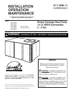
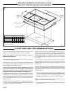
These units are designed for outdoor installation. For proper instal-
lation, the following recommendations must be considered.
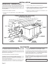
NOTE: Unit shipped for horizontal installation. Convert to
downflow per instruction.
The discharge air from the condenser fans must be unrestricted for
a minimum of 3 feet above the unit.
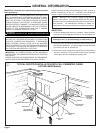
Roof Mounting Curb (field assembled BAYCURB030A and
BAYCURB033A, BAYCURB034A) or a field fabricated curb must be
in place before unit is hoisted to the roof.
Roof Mounting Curb (frame) must be installed on a flat, level
section of the roof (max. of 1/4" per foot pitch), providing a level
mounting surface for the unit. In addition, provide sufficient
height above the roof to prevent water from entering unit.
In locations where deep snows are encountered,RAlSE THE UNlT
A MINIMUM OF 12" OFF THE ROOF, DECK OR SLAB—the chance
of the coil being blocked with snow will be reduced. The water that
occurs during the defrost has a better chance of flowing from the
vicinity of the unit.
Roof Mounting Curb used with WCY—F models is approximately
14" high. This is normally sufficient height to prevent snow blockage
and additional clearance is not necessary.
AVOID LOCATING THE UNIT WHERE SNOW TENDS TO DRIFT.
This will reduce the times when it is necessary for the customer to
remove the snow from around the unit. MAKE CERTAIN THE
CUSTOMER KNOWS THAT SNOW ACCUMULATIONS SHOULD
BE REMOVED FROM THE SIDES OF THE UNIT FOR BEST
EFFICIENCY.
A snow drift barrier may be installed around the unit to prevent a
build up of snow on the sides of the unit. The barrier should be of
sufficient distance from the unit to prevent restriction of airflow to
and from unit.
LOCATE THE UNIT SO THAT THE WATER VAPOR THAT DIS-
CHARGES UPWARD DURING DEFROST DOES NOT CONDENSE
ON WINDOWS AND FOG THEM OR CAUSE ICICLES TO FORM
ON OVERHANGS.
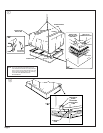
1. Be sure the mounting curb spans structural members (trusses)
of the roof, thereby providing sufficient support for weight of the
unit, curb and duct(s) plus any accessories (factory or field
installed). See Figures 1, 2, 3, 4, 5, 6, 7, 8, 9,10,11 and 12.
NOTE: If any internal accessories are to be added to the unit it
should be done at the shop if at all practical.
2. Unit should be positioned so Roof-Run-Off water does not pour
directly on unit.
6
E
F
HOLE IN ROOF
WOOD NAILER
SIDE RAIL
SERVICE
CLEARANCE
LINES
SERVICE
CLEARANCE
LINES
A
B
C
D
SUPPLY AIR
RETURN AIR
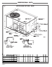
SERVICE CLEARANCE & PENETRATION DIMENSIONS
MODEL NO. A B C D E F
WCY024-030G 30" 30" *12" 24" 36" 25
"
WCY036-042G 30" 30" *12" 30" 44" 25
"
WCY048-060G 42" 30" *12" 36" 50" 25
"
* 18" WITH FRESH AIR ACCESSORY
* 30" WITH ECONOMIZER