


VAV-SVX02B-EN
Calibration
Procedures
Calibration Procedure (Steps 1–4 apply to all thermostat models)
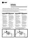
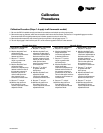
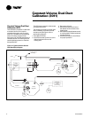
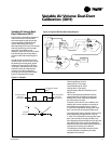
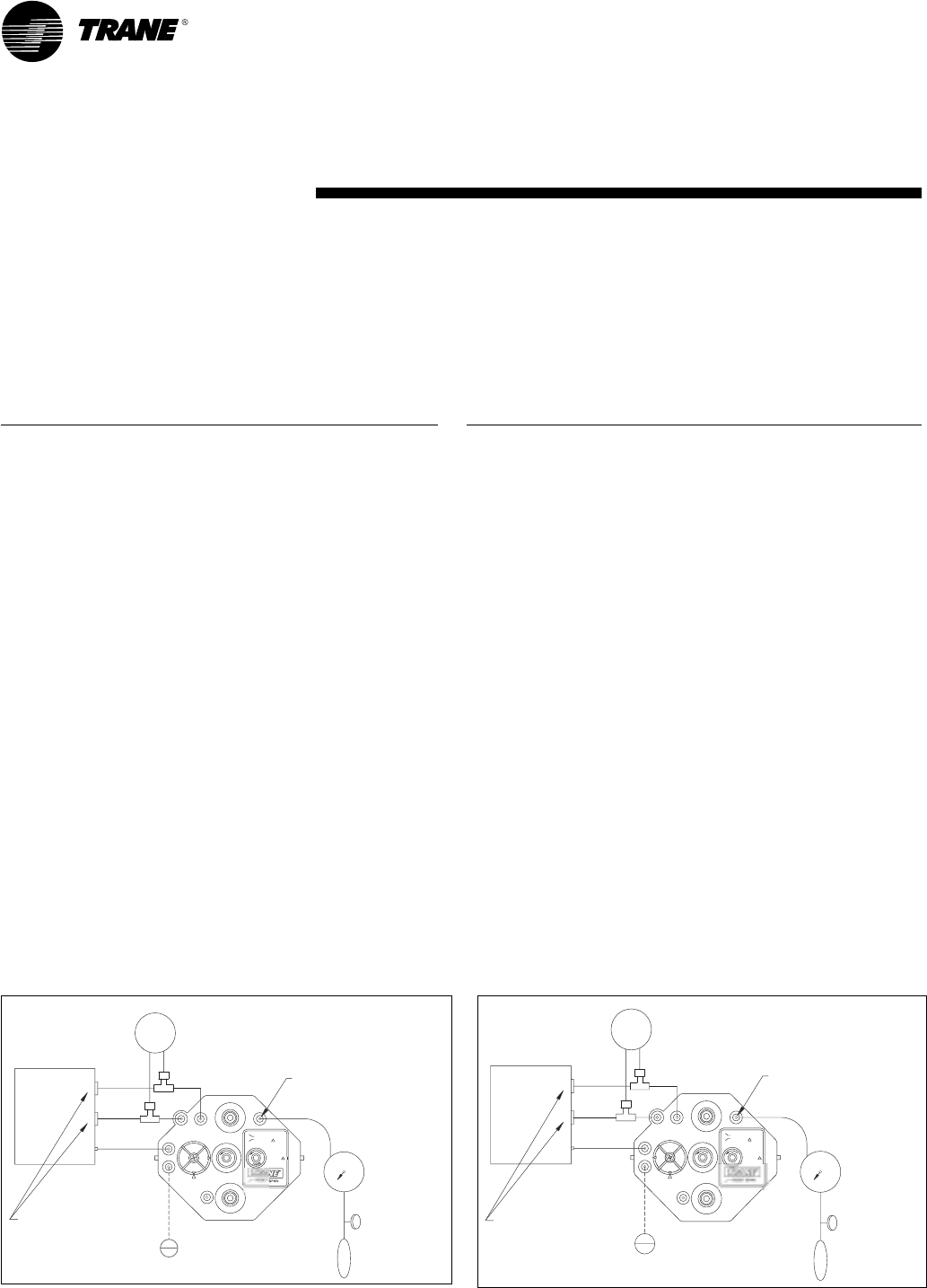
1. Be sure the PVR is installed correctly and that all connections are hooked up to the proper ports. See Figure 9 for unit application.
2. Remove the caps on the tees which are connected to the lines to the flow sensor. Connect a 0–2" magnehelic gage to monitor
flow sensor delta P. The higher-pressure port is further upstream on the air valve inlet.
3. Remove the thermostat line and connect a hand pump with a 0–20 psi gage to port “T”.
4. Tee a 0–20 psi gage in the line from port “B” on the volume regulator to the air valve actuator.
Figure 13–Connections of Direct/Reverse-Acting
Thermostat with Normally-Open Valve
Figure 14–Connections of Direct/Reverse-Acting
Thermostat with Normally-Closed Valve
8
Direct-Acting Thermostat
(See Figure 13 for proper
connections)
5. Set port “T” at 0 psi.
6. Monitor the delta P and
adjust the LO-stat mini-
mum) adjustment to
desired minimum.
7. Set port “T” input at 16
psi or greater with the
hand pump.
8. Monitor the delta P and
adjust the HI-stat (maxi-
mum) adjustment to
desired maximum flow. If
the actuator pressure is
less than 3 psi, the air
valve is wide open and
duct pressure must
increase to increase flow.
9. Set port “T” at 0 psi.
10.Monitor the minimum
flow delta P. If it is not
correct, adjust the LO-stat
adjustment knob.
Direct-Acting Thermostat
(See Figure 14 for proper
connections):
5. Set port “T” at 0 psi.
6. Monitor the delta P and
adjust the LO-stat (mini-
mum) adjustment to
desired minimum.
7. Set port “T” input at
16 psi or greater with the
hand pump.
8. Monitor the delta P and
adjust the HI-stat
(maximum) adjustment
to desired maximum flow.
If the actuator pressure is
greater than 13 psi, the air
valve is wide open and duct
pressure must increase to
increase flow.
9. Set port “T” at 0 psi.
10.Monitor the minimum
flow delta P. If it is not
correct, adjust the LO-stat
adjustment knob.
Normally-Open Valve
Normally-Open Valve
Reverse-Acting Thermostat
(See Figure 13 for proper
connections):
5. Set port “T” at 0 psi.
6. Monitor the delta P and
adjust the LO-stat delta P
(maximum) adjustment to
desired maximum. If the
actuator pressure is less
than 3 psi, the air valve is
wide open and duct
pressure must increase to
increase flow.
7. Set prot “T” to 16 psi
or greater with the
hand pump.
8. Monitor the delta P and
adjust the HI-stat (mini-
mum) adjustment to
desired minimum flow.
9. Set port “T” at 0 psi.
10.Monitor the maximum
flow delta P. If it is not
correct, adjust the LO-stat
adjustment knob.
Reverse-Acting Thermostat
(See Figure 14 for proper
connections):
5. Set port “T” at 0 psi.
6. Monitor the delta P and
adjust the LO-stat delta P
(maximum) adjustment to
desired maximum flow. If
the actuator pressure is
greater than 13 psi, the air
valve is wide open and
duct pressure must
increase to increase flow.
7. Set prot “T” to 16 psi
or greater with the
hand pump.
8. Monitor the delta P and
adjust the HI-stat (mini-
mum) adjustment to
desired minimum flow.
9. Set port “T” at 0 psi.
10.Monitor the maximum
flow delta P. If it is not
correct, adjust the LO-stat
adjustment knob.
0–2' Magnahelic Gage
C
R
C
R
C
LO
HI
Normally-Open Unit
Airflow Sensor
LO
Actuator
HI
NC
DAMPER
NO
M
20
S
G
I
N
C
N
C
B
H
Connect Hand Pump
Connect 0–20 psi Gage
Apply 20 psi
HI STAT
P
P
LO STAT
RESET START
P
T
PSI
0 10
Handpump
0–2 psi
Volume
Regulator
C
R
C
R
C
0–2' Magnahelic Gage
LO
HI
Normally-Closed Unit
Airflow Sensor
LO
Actuator
HI
S
20
NC
DAMPER
B
M
NO
H
G
I
N
C
N
C
Connect 0–20 psi Gage
Connect Hand Pump
Apply 20 psi
LO STAT
RESET START
I
N
R
C
N
R
C
R
HI STAT
P
P
T
PSI
0 10
0–2 psi
Handpump
Volume
Regulator