


VAV-SVX02B-EN 15
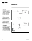
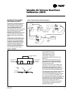
Thermostat Range: 3–8 psi
Heating Valve = 5 psi range
Thermostat Range: 8–13 psi
Cooling Valve = 5 psi range
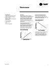
Approximately 1000 cfm divided by 5 psi =
200 cfm/1b*
*Due to the relationship between velocity
pressure and cfm; for both the cooling and
heating PVR, a linear relationship between
cfm and psi does not exist.
To obtain a unit minimum cfm of 400 cfm, the
heating deck volume regulator must have its
thermostat range changed from 3–8 psi to
4–9 psi. This is adjusted by changing the “reset
start” point from 3 psi to approximately 4 psi.
The cooling deck volume regulator must have its
thermostat range changed from 8–13 psi to
7–12 psi. This is adjusted by changing the “reset
start” point from 8 psi to approximately 7 psi.
By overlapping the thermostat spring ranges, we
were able to have 0 cfm minimum settings on
both the heat and cool deck and still maintain the
required unit minimum cfm of 400 cfm.
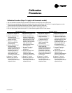
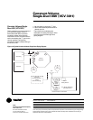
The calibration of the PVR is the same as the
normal calibration procedures previously
described in this manual.
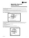
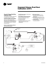
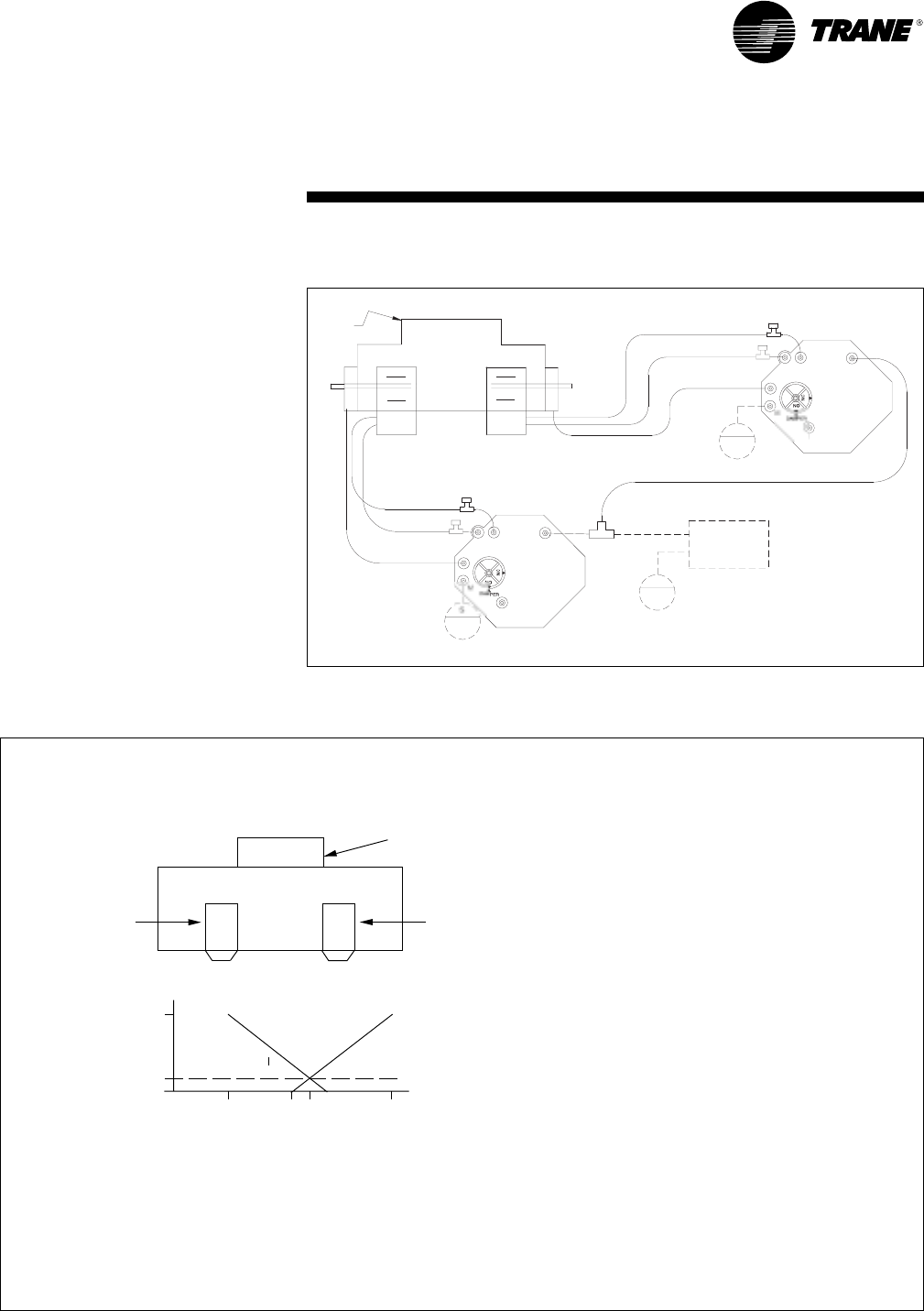
Figure 17–Example
Variable-Air-Volume Dual-
Duct Calibration (3011)
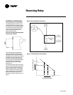
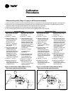
Figure 16 is a typical piping diagram of
a VAV dual-duct unit. The unit has a
thermostat piped to both pneumatic
volume regulators (PVR) which will
operate the heating deck from a
thermostat signal of 3–8 psi. The cooling
deck will operate from a thermostat
signal of 8–13 psi. With normal
calibration of the PVR, the unit will have
both the heating and cooling deck at
minimum with a thermostat signal of
8 psi.
In order to have a unit minimum cfm
and still have 0 cfm minimums on both
the heating and cooling deck, special
calibration is required. The PVR has a
“reset start” adjustment knob, which
allows the unit to be calibrated to a
minimum cfm. This is achieved by
crossing over the thermostat ranges.
Figure 17 illustrates this concept.
Figure 16–Typical VAV Dual-Duct Piping Diagram
Variable Air Volume Dual-Duct
Calibration (3011)
(137.9)
20
20
(137.9)
S
20
(137.9)
S
Two-Pipe
Remote-Mounted
T-Stat
(Direct-Acting)
Restrictor
Tee
Volume
Regulator
Actuator
HI
Outlet
Heating
V
a
l
ve
g
V l
Normally-
O
penO
LO
Normally-
O
penO
Cooling
V
a
l
ve
g
V l
LO
HI
L
H
B
G
T
B
G
H
L
T
Actuator
Volume
Regulator
N.O. Cooling Valve
Min 0 cfm
Max 1000 cfm
N.O. Heating Valve
Min 0 cfm
Max 1000 cfm
Unit Minimum 400 cfm
Max
Unit Min
Valve Min
47912
8