12 18-CD19D6-32
Installer’s Guide
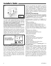
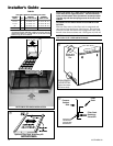
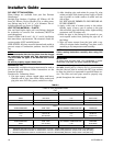
VIEW
ENGAGEMENT
HOLE DETAIL
(Typical both sides
and blower deck)
Blower Deck
Engagement
Hole
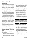
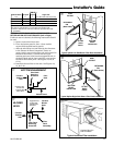
NOTE: The narrow 14.5" width furnace cabinet prevents use
of the filter rack for right side return. Pre-drill clearance
holes and then attach filter clips with the screws provided.
The filter clip with the leaf spring mounts in the rear of the
cabinet
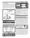
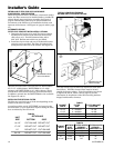
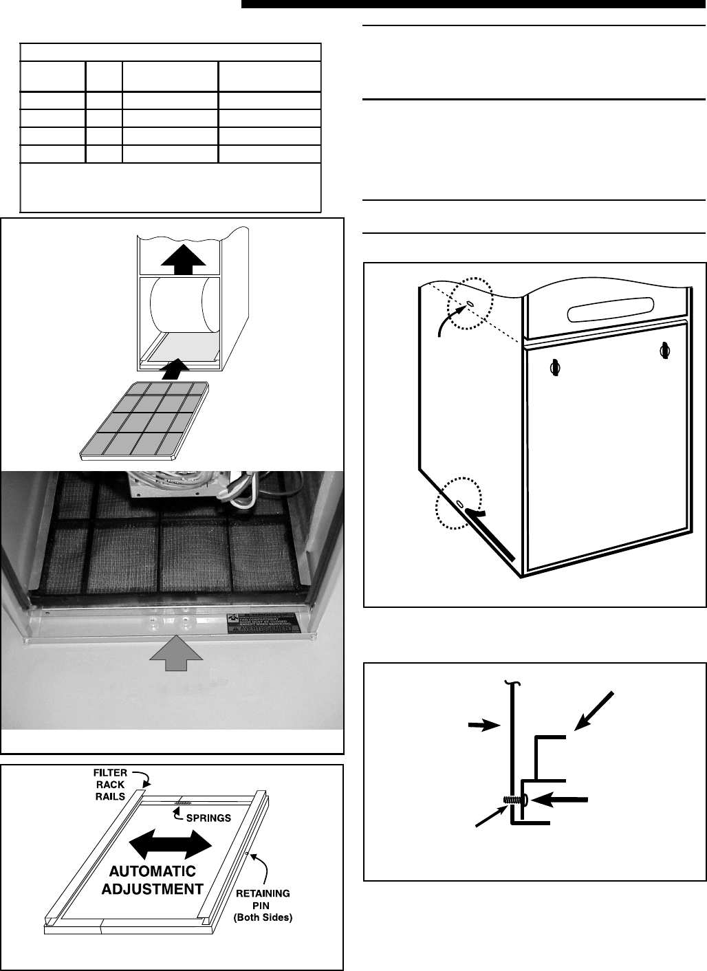
OPTIONAL FILTER RACK INSTALLATION FOR BOTTOM
RETURN
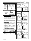
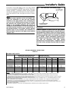
With the filter removed, the filter rack is compressed and
then inserted into the bottom of the furnace. The retaining
screw/pin on each side inserts into engagement holes at the
bottom of the furnace cabinet side. See Figures 13, 14 & 16.
NOTE: Remove the bottom front channel to install the filter
rack in the 14-1/2" width cabinet furnaces.
Filter
Rack
Furnace
Cabinet
Side
Filter Rack
Retaining
Screw/Pin
Engagement Hole
For
Bottom Return
Filter Rack
Installation With
t
y
Optional Filter Rack Accessory Kit
r
Airflow
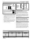
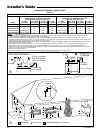
TABLE 4
UPFLOW FURNACE RETURN AIR FILTERS
CABINET
WIDTH
QTY*
CABINET
BOTTOM FILTER
CABINET
SIDE FILTER
14-1/2" 1 14" X 25" X 1" 17-1/2" X 25" X 1"
17-1/2" 1 17" X 25" X 1" 17-1/2" X 25" X 1"
21" 1 20" X 25" X 1" 17-1/2" X 25" X 1"
24-1/2" 1 24" X 25" X 1" 17-1/2" X 25" X 1"
**NOTE: For upflow 5 ton airflow models where the airflow
requirement exceeds 1800 CFM - Models will require return air
openings and filters on: (1) both sides, or (2) one side and the
bottom, or (3) just on the bottom
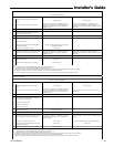
BAYRACK960A
BOTTOM FILTER RACK INSTALLATION
Airflow
e


