


10 18-CD19D6-32
Installer’s Guide
DUCT CONNECTIONS
Air duct systems should be installed in accordance with
standards for air conditioning systems, National Fire
Protection Association Pamphlet No. 90. They should
be sized in accordance with ACCA Manual D or which-
ever is applicable.
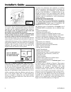
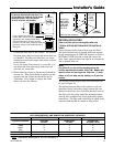
Central furnaces, when used in connection with cooling
units, shall be installed in parallel or on the upstream
side of the cooling coil to avoid condensation in the heat
exchanger. With a parallel flow arrangement, the damp-
ers or other means used to control flow of air shall be
adequate to prevent chilled air from entering the fur-
nace, and if manually operated, must be equipped with
means to prevent operation of either unit unless the
damper is in full heat or cool position.
On any job, flexible connections of nonflammable mate-
rial may be used for return air and discharge connections
to prevent transmission of vibration. Though these units
have been specifically designed for quiet, vibration free
operation, air ducts can act as sounding boards and could,
if poorly installed, amplify the slightest vibration to the
annoyance level.
When the furnace is located in a utility room adjacent
to the living area, the system should be carefully de-
signed with returns to minimize noise transmission
through the return air grille. Although these furnaces
are designed with large blowers operating at moderate
speeds, any blower moving a high volume of air will
produce audible noise which could be objectionable
when the unit is located very close to a living area. It is
often advisable to route the return air ducts under the
floor or through the attic. Such design permits the in-
stallation of air return remote from the living area
(i.e. central hall).
When the furnace is installed so that the supply ducts
carry air circulated by the furnace to areas outside the
space containing the furnace, the return air shall also
be handled by a duct(s) sealed to the furnace and termi-
nating outside the space containing the furnace.
RETURN AIR DUCT CONNECTION
NOTE:
On upflow 5 or 6 ton airflow models where the
airflow requirement exceeds 1800 CFM - Models will
require return air openings and filters on: (1) both
sides; or (2) one side and the bottom; or (3) just the
bottom.
All return air duct systems should provide for installa-
tion of return air filters.
1. Determine the appropriate position to set the
furnace in order to connect to the existing supply
and return ductwork.
2. For side return installations on upflow models,
remove the insulation around the opening in the
blower compartment.
NOTE:
Minimum return air temperature is 55° F.
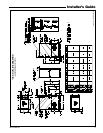
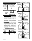
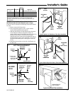
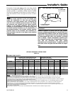
3. The side panels on upflow furnaces include locating
notches which may be used as guides for cutting an
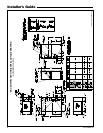
opening for return air. Refer to Figure 12 and the
outline drawing on page 5 for duct connection
dimensions for various furnaces.
4. If a 3/4" flange is to be used for attaching the air
inlet duct, add to cut where indicated by dashed
lines in Figure 12. Cut corners diagonally and bend
outward to form flange.
5. If flanges are not required, and a filter frame is
installed, cut along knockout guidelines.
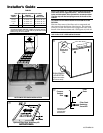
6. Upflow Furnaces: Use the optional filter rack on
either side or on the bottom if the filter is to be
used within the furnace cabinet.
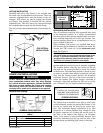
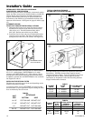
When the upflow furnace is installed in the horizon-
tal right or left application and a return duct is
attached to the top side as shown in Figure 11,
install the filter in a remote location.
Do not install the filter in the return duct directly
above the furnace in horizontal applications.
▲
WARNING
!
TO PREVENT INJURY OR DEATH DUE TO CONTACT
WITH MOVING PARTS, TURN THE POWER TO THE
FURNACE OFF BEFORE SERVICING FILTERS.
▲
WARNING
!
Do not install the filter in the return duct directly above the
furnace in horizontal applications. Install the filter remotely.
Installing the filter directly above the furnace in horizontal
applications may cause property damage, serious injury or
death.
When the upflow furnace is installed in the horizon-
tal right or left application and a close coupled (less
than 36") return duct is attached to the bottom side
of the furnace as shown in Figure 11, securely
attach a 1/2" mesh metal hardware cloth protective
screen to the inside bottom of the filter grill to
prevent personal injury from contacting
moving parts when reaching into the return
opening to replace the filter.
Close coupled (less than 36") return (filter directly
beneath bottom side return) is not recommended
due to noise considerations.
Downflow Furnaces: Brackets are factory
supplied to mount filters in the return air duct
work.