84 RTAC-SVX01F-EN
Installation - Electrical
When the chiller is not running the CWS is reset immediately (within one minute) for
Return Reset and at a rate of 1 degree F every 5 minutes for Outdoor Reset. The
chiller will start at the Differential to Start value above a fully reset CWS or CWS' for
both Return and Outdoor Reset.
Communications Interface options
Optional Tracer Communications Interface
This option allows the Tracer CH530 controller to exchange information (e.g. operating
setpoints and Auto/Standby commands) with a higher-level control device, such as a
Tracer Summit or a multiple-machine controller. A shielded, twisted pair connection
establishes the bi-directional communications link between the Tracer CH530 and the
building automation system.
To prevent control malfunctions, do not run low voltage wiring (<30 V) in
conduit with conductors carrying more than 30 volts.
Field wiring for the communication link must meet the following requirements:
• All wiring must be in accordance with the NEC and local codes.
• Communication link wiring must be shielded, twisted pair wiring (Belden 8760 or
equivalent). See the table below for wire size selection:
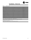
Wire Size Maximum Length of Communication Wire
• The communication link cannot pass between buildings.
• All units on the communication link can be connected in a “daisy chain”
configuration.
LonTalk Communications Interface for Chillers (LCI-C)
CH530 provides an optional LonTalk Communication Interface (LCI-C) between the
chiller and a Building Automation System (BAS). An LCI-C LLID shall be used to
provide "gateway" functionality between a LonTalk compatible device and the Chiller.
The inputs/outputs include both mandatory and optional network variables as
established by the LonMark Functional Chiller Profile 8040.
Installation Recommendations
• 22 AWG Level 4 unshielded communication wire recommended for most LCI-C
installations
• LCI-C link limits: 4500 feet, 60 devices
• Termination resistors are required
– 105 ohms at each end for Level 4 wire
– 82 ohms at each end for Trane "purple" wire
• LCI-C topology should be daisy chain
• Zone sensor communication stubs limited to 8 per link, 50 feet each (maximum)
• One repeater can be used for an additional 4500 feet, 60 devices, 8
communication stubs
Table 23 Wire Size
14 AWG (2.5 mm
2
) 5,000 FT (1525 m)
16 AWG (1.5 mm
2
) 2,000 FT (610 m)
18 AWG (1.0 mm
2
) 1,000 FT (305 m)


