


90 SS-SVX09A-EN
System Start-Up
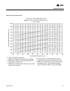
3. Plot this value onto the appropriate component pressure drop curve that shipped with the Air
Handling equipment. Use the data to assist in calculating a new fan drive if the CFM is not at
design specifications.
4. Plug the holes after the proper CFM has been established.
Turn the 115 volt control circuit switch 1S2 to the “OFF” position and open the field provided or
optional factory mounted disconnect switch.
After all adjustments have been made, proceed through the following procedures.
Compressor Start-Up (All Systems)
ƽ CAUTION
Compressor Damage!
Do not allow liquid refrigerant to enter the suction line. Excessive liquid accumulation in the
liquid lines may result in compressor damage.
1. Before closing the field provided or optional factory mounted disconnect switch at the unit,
ensure that the compressor discharge service valve and the liquid line service valve for each
circuit is back seated.
COMPRESSOR SERVICE VALVES MUST BE FULLY OPENED BEFORE START-UP (SUCTION,
DISCHARGE, LIQUID LINE, AND OIL LINE).
2. If the system has been previously charged before starting, disable the compressor(s) by
unplugging the reset relay for each circuit. Refer to the unit-wiring diagram that sipped with the
unit. Turn the main power disconnect to the “On” position and allow the crankcase heater to
operate a minimum of 8 hours before continuing.
NOTICE
Compressor Damage could occur if the crankcase heater is not allowed to operate the minimum
8 hours before starting the compressor(s).
3. Attach a set of service gauges onto the suction and discharge gauge ports for each circuit.
4. Charge liquid refrigerant into the liquid line of each refrigerant circuit with the required amount
of R-22. Refrigerant should be charged into the system by weight. Use an accurate scale or a
charging cylinder to monitor the amount of refrigerant entering the system. Refer to
Table 14
for the required amount of refrigerant for the condensing unit.
If the pressure within the system equalizes with the pressure in the charging cylinder before
charging is completed, complete the process by charging into the suction (low) side of the
system after the system has been started.
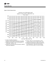
Table 15 gives the minimum starting temperatures for both “Standard” & “Low” Ambient
units.
Do not attempt to charge the system with the low ambient dampers and/or hot gas bypass
operating (if applicable). Disable the low ambient dampers in the “Open” position (refer to the
“Low Ambient Damper Adjustment” section) and de-energize the hot gas bypass solenoid
valves before proceeding.
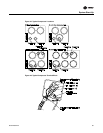
5. On units with dual circuits, start only one circuit at a time. To disable the compressors, unplug
the appropriate lockout relay inside the unit control panel. Refer to
Table 16 for the compressor
sequencing and Figure 45 for their location.
6. Close the “High Side” valve on the manifold gauge set.
7. Set the “System” selection switch to the “Cool” position