52 SS-SVX09A-EN
Installation
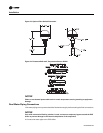
These components may include:
Field installed Discharge Duct Sensor (6RT1 CV units);
Field installed Return Duct Sensor (6RT6 CV units);
Field installed Discharge Air Sensor (6RT3 VAV units);
Field installed Chilled Water Sensor (6RT2 EVP units);
1. Wiring for the components utilizing a DC analog input\output signal must be shielded cable
(Belden 8760 or equivalent). Ground the shield at one end only.
2. Tab le 10 lists the conductor sizing guidelines that must be followed when interconnecting a DC
binary output device to the unit.
Note: Resistance in excess of 2.5 ohms per conductor can cause deviations in the accuracy of the
controls.
3. Ensure that the wiring between the binary controls and the unit’s termination point does not
exceed two and a half (2.5) ohms/conductor for the length of the run.
4. Do not run the electrical wires transporting DC signals in or around conduit housing high
voltage wires.
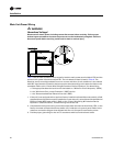
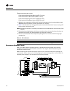
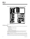
Economizer Actuator Circuit
Each unit ordered with the Constant Volume or Variable Air Volume control option has the
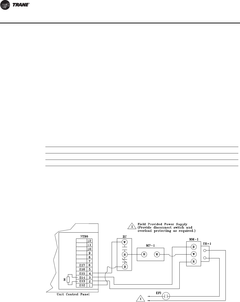
capability of controlling a field installed economizer. The diagram below illustrates a typical
economizer actuator circuit.
When connecting the economizer actuator control circuit to the terminal board inside the unit
control panel, refer to the actual unit wiring diagram for terminal designation, i.e. W, B, R, & Y. A
separate power supply for the actuator(s) must be field provided.
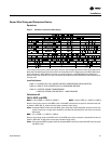
Table 10. DC Conductors
Distance from Unit to Control Recommended Wire Size
000 - 499 feet 16 gauge
500 - 1000feet 14 gauge


