


SCXG-SVX01B-EN 47
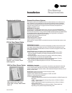
Variable Frequency Drive
Option (VFD)
The variable frequency drive (VFD)
option can only be used with IntelliPak
units. The VFD and VFD w/bypass is
available from 7.5 to 25 hp and is a
Square D model Altivar 58. All VFDs are
pre-configured and run-tested at the
factory prior to shipping. The VFD is wall
mounted. For more information on the
VFD, see the manuals that ship with each
VFD:
Altivar 58 Adjustable Speed Drive
Controllers Keypad Display
and
Altivar 58 Adjustable Speed Drive
Controllers Installation Guide Type H
Controllers.
___________________________________________________________________________________
Control and line voltage wiring
from the VFD to the unit must be
in accordance with all local and
National Electric Codes. Do not
touch circuit components until
main power has been turned off
and “charge” lamp is
extinguished. The capacitors are
still charged and can be quite
dangerous.
________________________________________________________________________________
Disconnect electrical power
source to prevent injury or death
from electric shock. Do not
connect or disconnect wires and
connectors while power is
applied to the circuit.
Pre-Startup
RequirementsInstallation
______________________________________________________________
Use only copper conductors for
electrical unit connections to
prevent equipment damage.
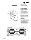
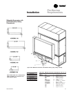
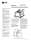
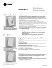
VFD Mounting Requirements
Proper location of the VFD is important to
achieve proper performance and normal
operating life. Installation must be in an
area where it will be protected from:
• Direct sunlight, rain or moisture.
• Corrosive gases or liquids.
• Vibration, airborne dust, or metallic
particles.
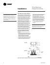
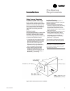
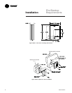
For effective cooling as well as proper
maintenance, install the VFD vertically to
the ground using four mounting screws.
There must be a minimum eight inch
clearance above and below the VFD. A
minimum two inch clearance is required
on each side.
Also, allow enough clearance for opening
the VFD cabinet door. This will ensure
sufficient air space for cooling.
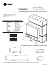
Refer to the “Dimensions and Weights”
sections on pages 28-30 for VFD
dimensions and weights.
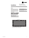
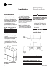
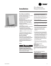
VFD Electrical Installation Procedure
Refer to the
National Electric Code,
section 310-16
for sizing wires 4B - 9B. All
other control wires should be twisted
shielded or twisted pair shielded, 20 - 14
AWG, with lead length not to exceed 164
feet. When using shielded wire, the shield
sheath must be connected at the VFD
only. The connection on units with VFD
only is J13-S. On units with VFD w/
bypass, the connection is ITB1-10.
ƽƽ
ƽƽ
ƽ
WARNING
!
ƽƽ
ƽƽ
ƽ
WARNING
!
ƽƽ
ƽƽ
ƽ
CAUTION
!