


34 SCXG-SVX01B-EN
Mechanical
Requirements
Water Piping
Note: To prevent water damage, install all
piping drain and vent plugs.
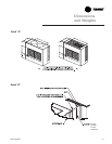
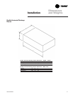
Condenser Connections
Condenser water piping knockouts are in
the lower left end panel. If necessary,
remove insulation to gain access. All field
installed piping must conform to
applicable local, state, and federal codes.
To complete condenser water
connections follow the procedure below.
Note: Four condenser waterline drain
plugs ship in a bag in the unit’s left end.
The installer must field install these four
plugs using pipe thread sealer. An addi-
tional plug are provided for units with a
waterside economizer.
1. Install the vent plugs in the economizer
coil headers and condenser manifolds.
These plugs ship in a bag with the
condenser drain plugs.
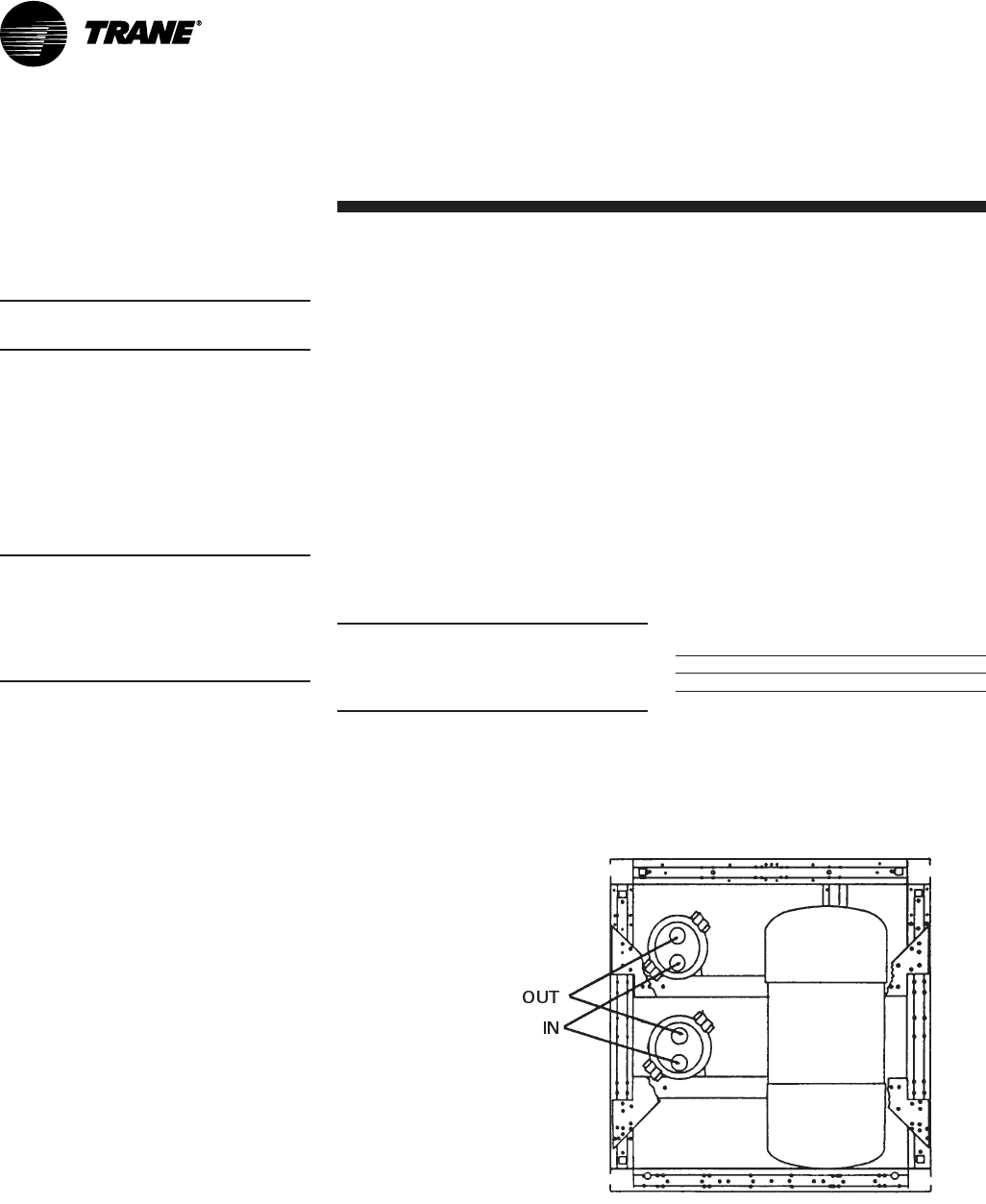
2. Attach the water supply line to the inlet
connection, and the return line to the
outlet connection. Entering and leaving
water connections for all condensers
are factory manifolded and require only
single connections for entering and
leaving water. If the unit has a
waterside economizer and/or control
valves, the factory pipes between these
components.
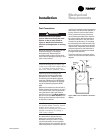
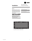
3. If using a cooling tower, refer to Figure
I-MR-3 on page 35 for a typical piping
circuit from the unit. For typical city or
well water piping, see Figure I-MR-4 on
page 35.
4. Ensure the water pressure to the unit
does not exceed 400 psig.
Note: To prevent water pump damage,
design system piping to provide relief
when using energy saving waterside
economizer valves.
Installation
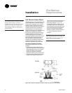
Condensate Drain Connections
The condensate drain is internally
trapped. Condensate drain connections
are on the unit’s left side. Connect
condensate drain piping to the 1
1
/
4
“ NPT
female fitting, using at least
7
/
8
” OD
copper or
3
/
4
“ OD iron pipe. Pitch the
condensate line downward a minimum of
1
/
2
” for each 10' of horizontal run, away
from the unit. Be sure to install the
condensate drain “P” trap drain plug.
Before starting the unit, fill the trap with
water to prevent negative pressure in the
fan section from impeding condensate
flow. To facilitate drain pipe cleaning,
install plugged tees in place of 90°
elbows.
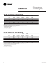
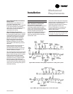
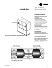
Table I-MR-1. Water Connection Sizes.
Unit Size Direct Condenser Factory Piped
SXWG 20-35 1
1
/
2
NPT 2
1
/
2
NPT
Figure I-MR-2. Direct condenser connections.