


18-BC61D1-1 5
Installer’s Guide
I. ELECTRIC HEATERS
Electric heaters, if used, are to be installed in the air han-
dling device according to the instructions accompanying the
air handler and the heaters.
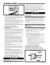
J. START CONTROL
Some models have quick start components which are factory
installed. For models that do not have factory installed start
components, provisions are made for a field installed start kit
accessory. When adding an accessory, follow the instructions
provided with the kit.
K. OUTDOOR THERMOSTAT
An outdoor thermostat TAYSTAT250B may be field installed.
For data, see wiring diagram attached to unit and instruction
sheet packaged with outdoor thermostat.
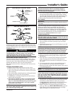
L. SEACOAST SALT SHIELD
Units installed within one (1) mile of salt water including
seacoasts and inland waterways, require the addition of
BAYSEAC001 (Seacoast Kit) at the time of installation.
IMPORTANT:
See Limited Warranty information in Use and Care Manual.
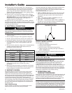
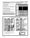
SYSTEM FAULTS
REFRIGERANT CIRCUIT
Head Pressure Too High
Head Pressure Too Low
Suction Pressure Too High
Suction Pressure Too Low
Liquid Refrig. Floodback (TXV)
I.D. Coil Frosting
Compressor Runs
Inadequate or No Cooling/Htg
ELECTRICAL
Compressor & O.D. Fan
Won’t Start
Compressor Will Not Start
But O.D. Fan Runs
O.D. Fan Won’t Start
Compressor Hums But Won’t Start
Compressor Cycles on IOL
I.D. Blower Won’t Start
DEFROST
Unit Won’t Initiate Defrost
Defrost Terminates on Time
Unit Icing Up
WHAT TO CHECK MODE
POWER SUPPLY
HIGH VOLTAGE WIRING
COMPRESSOR IOL
RUN CAPACITOR
START CAPACITOR
START RELAY
CONTACTOR CONTACTS
LOW VOLTAGE WIRING
CONTROL TRANSFORMER
THERMOSTAT
CONTACTOR COIL
LOW VOLTAGE FUSE
STUCK COMPRESSOR
INEFFICIENT COMP.
REF. UNDERCHARGE
REF. OVERCHARGE
EXCESSIVE EVAP. LOAD
NONCONDENSABLES
RES. O.D. AIRFLOW
O.D. AIR RECIRCULATION
TXV STUCK OPEN
SUPERHEAT
RES. I.D. AIRFLOW
REF. CIR. RESTRICTIONS
SOV LEAKING
SOV COIL DEFECTIVE
CHECK VALVE LEAKING
*
DEFROST RELAY DEF.
DEFROST CONTROL DEF.
C
H
C
H
C
H
C
H
C
H
C
H
C
H
C
H
C
H
C
H
C
H
C
H
C
H
C
H
C
H
C
H
P
P
P
P
P
P
P
P
P
P
P
P
P
P
S
S
S
S
S
S
S
S
S
S
S
S
S
S
S
S
S
S
S
S
S
S
S
S
S
S
S
S
P
P
P
P
S
S
S
S
P
P
P
P
S
S
P
P
P
P
P
P
P
P
P
P
P
P
P
P
S
S
S
S
S
S
S
S
P
P
P
P
P
P
P
P
P
P
P
P
P
P
P
P
P
P
P
S
S
S
S
S
S
S
P
S
S
S
S
S
S
S
S
S
S
S
S
P
P
S
S
S
S
S
S
S
S
S
S
P
P
P
P
P
S
S
S
S
S
S
S
S
S
S
S
P
P
S
S
S
S
S
S
S
P
P
P
P
P
P
P
S
S
PP
P
P
C - Cooling H - Heating P - Primary Causes S - Secondary Causes
*
- 3 Phase Only
TROUBLESHOOTING CHART — WHAT TO CHECK
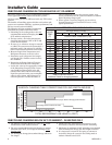
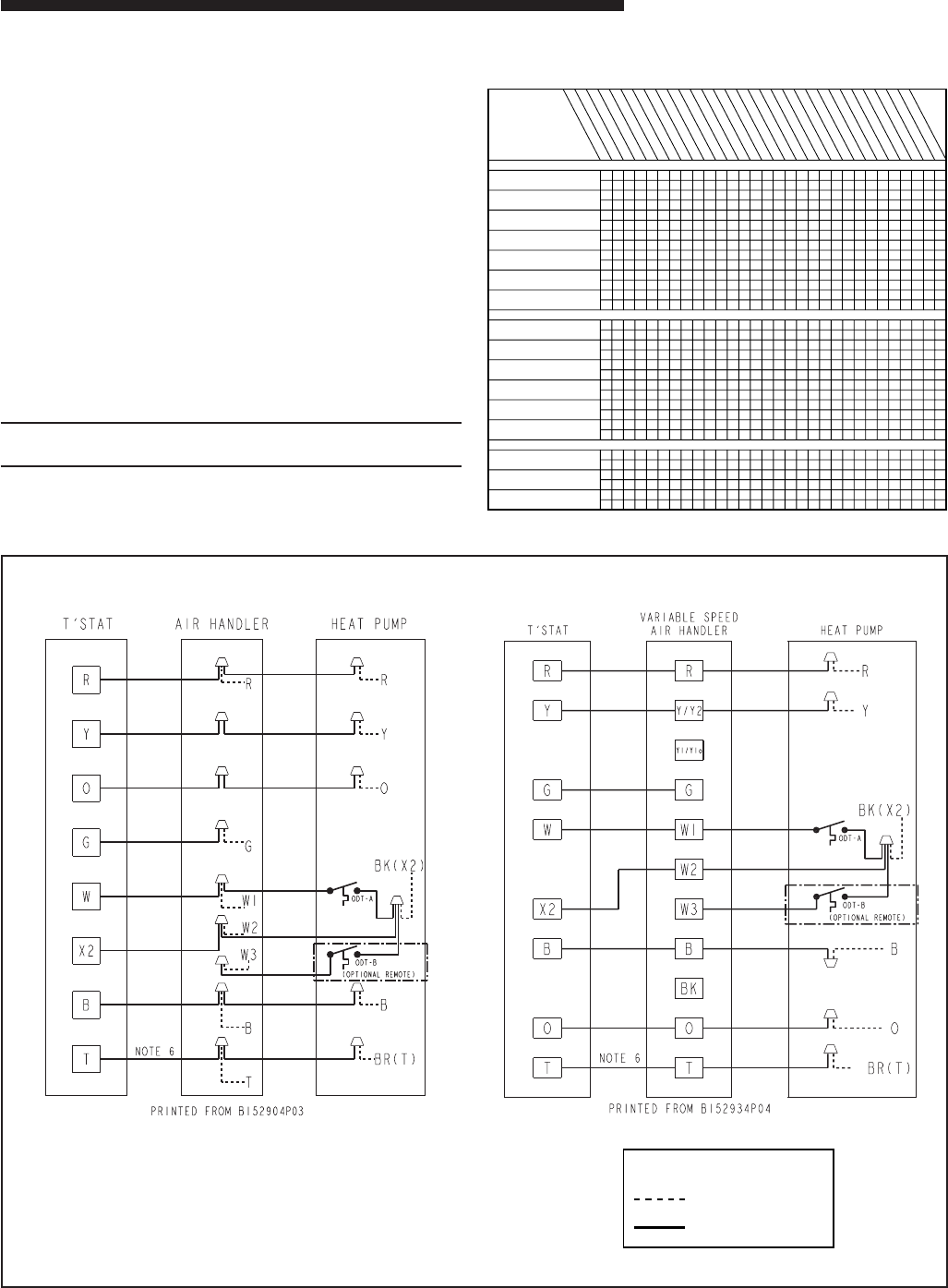
TYPICAL FIELD HOOK-UP DIAGRAMS
Notes:
1. Be sure power supply agrees with equipment nameplate.
2. Power wiring and grounding of equipment must comply with local codes.
3. Low voltage wiring to be No. 18 AWG minimum conductor.
4. ODT-B must be set lower than ODT-A.
5. If outdoor thermostats (ODT) are not used, connect W1 to W2 and W3.
6. N/A to programmable thermostat.
LEGEND
FACTORY WIRING
FIELD WIRING
M. TROUBLESHOOTING