4 18-BC61D1-1
Installer’s Guide
10. The gas valve can now be opened. For a ball type gas
valve, open the gas valve by removing the shut-off valve
cap and turning the valve stem 1/4 turn counterclock-
wise, using 1/4" Open End or Adjustable wrench. See
Figure 4. For brass gas line service valve opening, follow
8 and 9 on page 3. See Figure 5.
11. The gas valve is now open for refrigerant flow. Replace
valve stem cap to prevent leaks. Again, these caps MUST
BE REPLACED to prevent leaks. Replace valve stem
and pressure tap cap finger tight, then tighten an
additional 1/6 turn. See Figure 4.
If refrigerant lines are longer than 15 feet and/or a different
size than recommended, it will be necessary to adjust system
refrigerant charge upon completion of installation. See page 6
or in the unit Service Facts.
E. ELECTRICAL CONNECTIONS
WARNING
!
When installing or servicing this equipment, ALWAYS
exercise basic safety precautions to avoid the possibility
of electric shock.
1. Power wiring and grounding of equipment must comply
with local codes.
2. Power supply must agree with equipment nameplate.
3. Install a separate disconnect switch at the outdoor unit.
4. Ground the outdoor unit per local code requirements.
5. Provide flexible electrical conduit whenever vibration
transmission may create a noise problem within the
structure.
6. The use of color coded low voltage wire is recommended to
simplify connections between the outdoor unit, the
thermostat and the indoor unit.
Table 1 — NEC Class II Control Wiring
24 VOLTS
WIRE SIZE MAX. WIRE LENGTH
18 AWG 150 FT
16 AWG 225 FT.
14 AWG 300 FT.
7. Table 1 defines maximum total length of low voltage
wiring from outdoor unit, to indoor unit, and to
thermostat.
8. Mount the indoor thermostat in accordance with instruc-
tion included with the thermostat. Wire per appropriate
hook-up diagram (included in these instructions).
F. DEFROST CONTROL
The demand defrost control measures heat pump outdoor
ambient temperature with a sensor located outside the
outdoor coil. A second sensor located on the outdoor coil is
used to measure the coil temperature. The difference between
the ambient and the colder coil temperature is the difference
or delta-T measurement. This delta-T measurement is
representative of the operating state and relative capacity of
the heat pump system. By measuring the change in delta-T,
we can determine the need for defrost. The coil sensor also
serves to sense outdoor coil temperature for termination of
the defrost cycle.
FAULT IDENTIFICATION
A fault condition is indicated by the flashing light on the
defrost control inside the heat pump control box.
In normal operation, the defrost control light will flash once
each second. If the light is flashing more than once per
second or not at all, refer to the service manual for that unit.
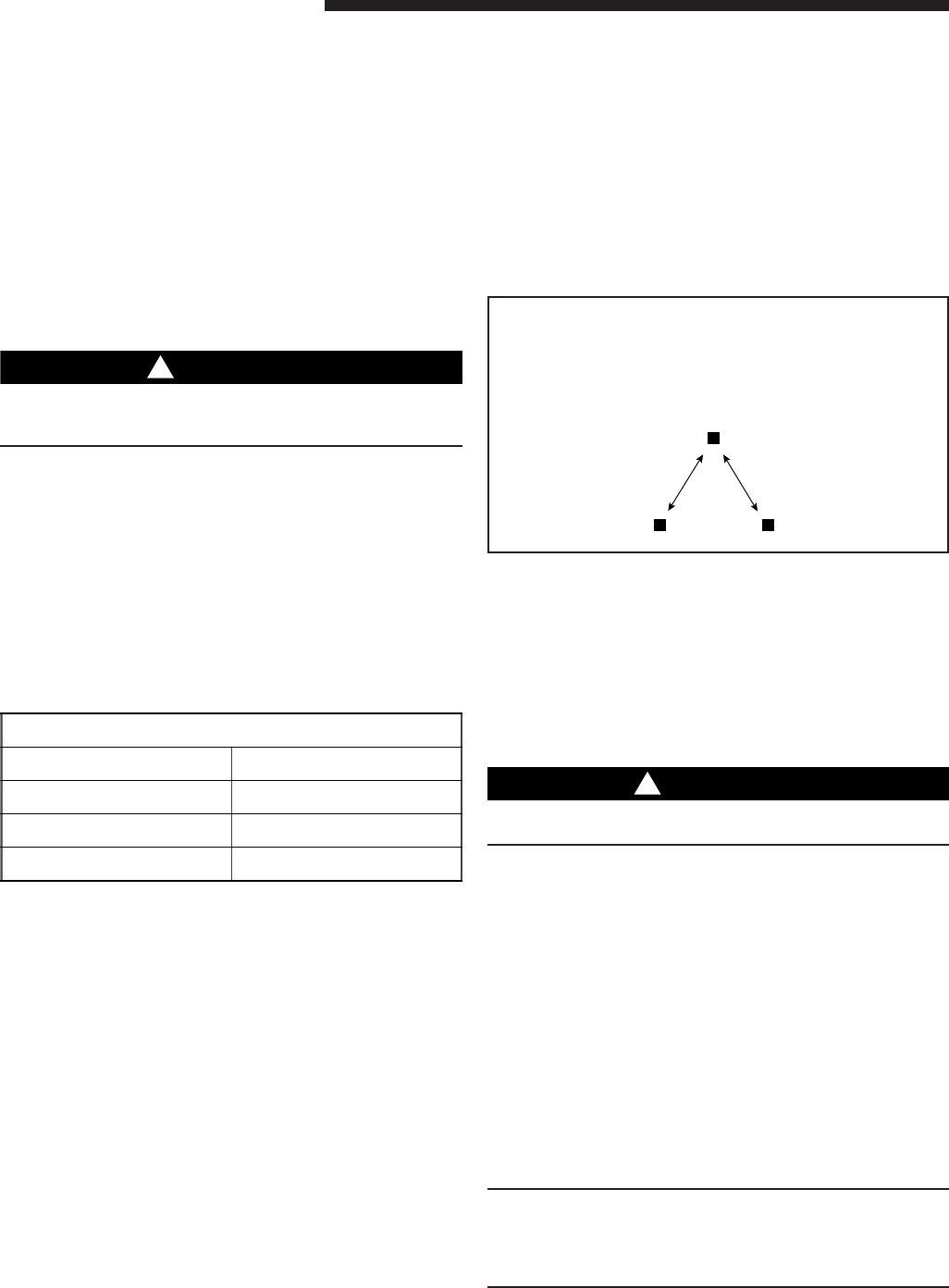
PIN IDENTIFICATION (See Figure 6.)
1. TEST_COMMON (Shorting any of the other pins to this
pin causes the function of the other pin to be executed.
Leaving this pin open results in the normal mode of
operation.)
2. TST = Test (Shorting TEST_COMMON to this pin
speeds up all defrost board timings.)
3. FRC_DFT = Forced Defrost (Short TEST_COMMON to
this pin for two [2] seconds to initiate a forced defrost.
Remove the short after defrost initiates.)
PIN IDENTIFICATION
6
DEFROST CONTROL CHECKOUT
Normal operation requires:
a. LED on board flashing 1 time/second.
b. 24V AC between R & B.
c. 24V AC between Y & B with unit operating.
d. Defrost initiation when FRC_DFT pin is shorted to
TEST_COMMON pin.
If a defrost control problem is suspected, refer to the service
information in control box.
WARNING
!
Do NOT connect 24V AC to T1 (ODS-A) terminal. ODS-A
thermistor WILL BE BLOWN.
G. COMPRESSOR START UP
After all electrical wiring is complete, SET THE THERMO-
STAT SYSTEM SWITCH IN THE OFF POSITION SO
COMPRESSOR WILL NOT RUN, and apply power by
closing the system main disconnect switch. This will activate
the compressor sump heat (where used). Do not change the
Thermostat System Switch until power has been applied for
one (1) hour. Following this procedure will prevent potential
compressor overload trip at the initial start-up.
H. OPERATIONAL AND
CHECKOUT PROCEDURES
Final phases of this installation are the unit Operational and
Checkout Procedures which are found in this instruction on
page 8. To obtain proper performance, all units must be
operated and charge adjustments made in accordance with
procedures found in the Service Facts and on page 6.
IMPORTANT:
Perform a final unit inspection to be sure that factory tubing has
not shifted during shipment. Adjust tubing if necessary so tubes
do not rub against each other when the unit runs. Also be sure
that wiring connections are tight and wire routing is secure.


