


4 18-AC56D1-1
Installer’s Guide
E. ELECTRICAL CONNECTIONS
WARNING
!
When installing or servicing this equipment, ALWAYS
exercise basic safety precautions to avoid the possibility of
electric shock.
1. Power wiring and grounding of equipment must comply
with local codes.
2. Power supply must agree with equipment nameplate.
3. Install a separate disconnect switch at the outdoor unit.
4. Ground the outdoor unit per local code requirements.
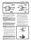
5. Provide flexible electrical conduit whenever vibration
transmission may create a noise problem within the
structure.
6. The use of color coded low voltage wire is recommended
to simplify connections between the outdoor unit, the
thermostat and the indoor unit.
Table 1 — NEC Class II Control Wiring
24 VOLTS
WIRE SIZE MAX. WIRE LENGTH
18 AWG 150 FT
16 AWG 225 FT.
14 AWG 300 FT.
7. Table 1 defines maximum total length of low voltage
wiring from outdoor unit, to indoor unit, and to thermostat.
8. Mount the indoor thermostat in accordance with instruc-
tion included with the thermostat. Wire per appropriate
hook-up diagram (included in these instructions).
F. COMPRESSOR START-UP
After all electrical wiring is complete, SET THE THERMO-
STAT SYSTEM SWITCH IN THE OFF POSITION SO
COMPRESSOR WILL NOT RUN, and apply power by
closing the system main disconnect switch. This will activate
the compressor sump heat (where used). Do not change the
Thermostat System Switch until power has been applied for
one (1) hour. Following this procedure will prevent potential
compressor overload trip at the initial start-up.
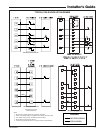
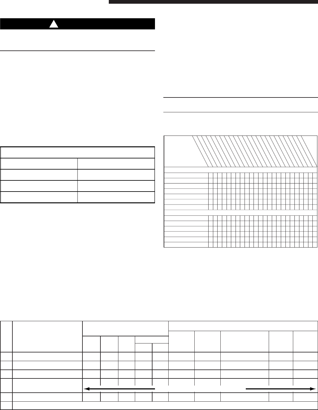
INDOOR THERMOSTAT
SWITCH SETTING
11
Fan Switch
TO CHECK Off Cool Heat Auto On
COMPONENT OPERATION
Indoor Outdoor
Compressor
3
Comp. Furnace
Blower Fan
Runs
Sump Heat
Runs Runs Heater Comes On
Step
No.
CHECKOUT PROCEDURE WITH MAIN POWER DISCONNECTS CLOSED (ON)
1
Also set thermostat dial to call for cooling or heating as necessary.
2
Check only necessary if heating unit is used for indoor section and wiring has been disturbed during installation of cooling equipment.
3
When applicable.
1 Sump Heat X X X
2 Indoor Fan Operation X X X X
3 Cooling Operation X X X X X X
4 Checking Performance X X X X X X
& Charge
USE CHARTS ATTACHED TO O.D. UNIT
5 Heating
2
XX X X X
6 Inform owner on how to operate system and what to expect of it. At the same time deliver Owner’s Use and Care Booklet.
G. OPERATIONAL AND
CHECKOUT PROCEDURES
Final phases of this installation are the unit Operational and
Checkout Procedures which are found in this instruction (see
table below and pages 6 and 8). To obtain proper perfor-
mance, all units must be operated and charge adjustments
made in accordance with procedures found on page 6 and in
the Service Facts.
H. SEACOAST SHIELD
Units installed within one mile of salt water, including
seacoasts and inland waterways, require the addition of
BAYSEAC001 (Seacoast Kit) at the time of installation.
IMPORTANT:
See Limited Warranty information in Use and Care Manual.
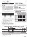
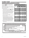
I. TROUBLESHOOTING
REFRIGERANT CIRCUIT
Liquid Pressure Too High
Liquid Pressure Too Low
Suction Pressure Too High
Suction Pressure Too Low
Liquid Refrig. Floodback TXV System
I.D. Coil Frosting
Compressor Runs Inadequate or No Cooling
ELECTRICAL
Compressor & O.D. Fan Do Not Start
Compressor Will Not Start But O.D. Fan Runs
O.D. Fan Won’t Start
Compressor Hums But Won’t Start
Compressor Cycles on IOL
I.D. Blower Won’t Start
SYSTEM FAULTS
P - Primary Causes S - Secondary Causes
P
P
P
S
S
PS
S
S
S
S
P
S
S
S
P
P
P
S
S
S
S
S
S
S
P
P
P
S
P
P
S
S
S
P
P
P
P
P
P
P
P
P
P
S
S
S
S
P
P
PP
P
S
S
PSPSS S S S
S
S
P
P
P
P
P
S
P
P
POW
ER SUPPLY
HIGH
VO
LTAG
E W
IR
IN
G
CO
MPR. IO
L
RU
N CAPACITOR
STAR
T CAPACITOR
START RELAY
CO
NTAC
TO
R CO
NTACTS
LO
W
VO
LTAGE W
IR
IN
G
CO
N
TR
O
L TRANSFO
RM
ER
C
ON
TAC
TOR
C
O
IL
LOW
VO
LTAGE FUSE
STU
CK C
O
M
PRESSO
R
INE
FFICI
ENT CO
M
PRESSO
R
REFRIG
ERANT U
N
DERC
HARG
E
REFR
IG
E
RAN
T OVERC
H
A
R
GE
EXCE
SS
IVE EVAP. LO
AD
NO
N
CO
N
DE
NSAB
LES
R
ESTRICTED
O.D
. AIR
FLO
W
O.D
. AIR REC
IR
C
ULATION
TXV S
T
U
C
K O
PEN
SUPERH
EA
T
RESTRICTED I.D. AIRFLO
W
REF. C
IRC
UIT RESTRICTIO
NS
O
.D
. FA
N SPEED
SW
ITCH
TROUBLESHOOTING CHART — WHAT TO CHECK