


18-AC56D1-1 3
Installer’s Guide
After the brazing operation of refrigerant lines to both the
outdoor and indoor unit is completed, the field brazed
connections must be checked for leaks. Pressurize through
the service valve ports, the indoor unit and field refrigerant
lines with dry nitrogen to 350-400 psi. Use soap bubbles or
other leak-checking methods to see that all field joints are
leak-free! If not, release pressure; then repair!
SYSTEM EVACUATION
NOTE:
Since the outdoor unit has a refrigerant charge, the gas and
liquid line valves must remain closed.
1. Upon completion of leak check, evacuate the refrigerant
lines and indoor coil before opening the gas and liquid
line valves.
2. Attach appropriate hoses from manifold gauge to gas
and liquid line pressure taps.
NOTE:
Unnecessary switching of hoses can be avoided and
complete evacuation of all lines leading to sealed system
can be accomplished with manifold center hose and
connecting branch hose to a cylinder of HCFC-22 and
vacuum pump.
3. Attach center hose of manifold gauges to vacuum pump.
4. Evacuate until the micron gauge reads no higher than
350 microns.
5. Close off valve to vacuum pump and observe the micron
gauge. If gauge pressure rises above 500 microns in one (1)
minute, then evacuation is incomplete or system has a leak.
6. If vacuum gauge does not rise above 500 microns in
one (1) minute, the evacuation should be complete.
7. With vacuum pump and micron gauge blanked off,
open valve on HCFC-22 cylinder and charge refriger-
ant lines and indoor coil with vapor to tank pressure
of HCFC-22 supply.
8. Close valve on HCFC-22 supply cylinder. Close valves
on manifold gauge set and remove refrigerant charging
hoses from liquid and gas pressure tap ports.
NOTE:
A 3/16" Allen wrench is required to open liquid line service
valve. A 1/4" Open End or Adjustable wrench is required to
open gas line valve. A 3/4" Open End wrench is required to
take off the valve stem cap.
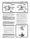
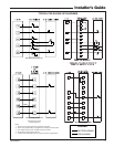
9. The liquid line shut-off valve can now be opened. Remove
shut-off valve cap. Fully insert hex wrench into the stem
and backout counterclockwise until valve stem just touches
rolled edge (approximately five [5] turns) observing
WARNING statement on page 2. See Figure 3.
10. Replace liquid service pressure tap port cap and valve
stem cap. These caps MUST BE REPLACED to
prevent leaks. Replace valve stem cap and pressure tap
cap finger tight, then tighten an additional 1/6 turn.
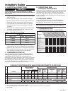
11. The gas valve can now be opened. Open the gas valve by
removing the shut-off valve cap and turning the valve
stem 1/4 turn counterclockwise, using 1/4" Open End or
Adjustable wrench. See Figure 4.
12. The gas valve is now open for refrigerant flow. Replace
valve stem cap to prevent leaks. Again, these caps
MUST BE REPLACED to prevent leaks. Replace valve
stem cap and pressure tap cap finger tight, then tighten
an additional 1/6 turn. See Figure 4.
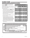
If refrigerant lines are longer than 15 feet and/or a
different size than recommended, it will be necessary to
adjust system refrigerant charge upon completion of
installation. See page 6 or in the unit Service Facts.
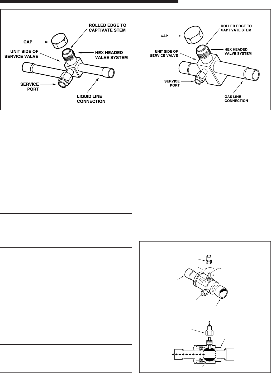
LIQUID LINE SERVICE VALVE
3
CAP
1/4 TURN ONLY
COUNTERCLOCKWISE
FOR FULL OPEN
POSITION
VALVE STEM
GAS LINE CONNECTION
UNIT SIDE
OF VALVE
CAP
BODY
COOLING
CORE
PRESSURE TAP PORT
GAS LINE BALL SERVICE VALVE
4
GAS LINE SERVICE VALVE