


© 2005 American Standard Inc. All Rights Reserved 18-AC56D1-1
Installer’s Guide
C. INSTALLING REFRIGERANT LINES
CAUTION
!
If using existing refrigerant lines make certain that all joints
are brazed, not soldered.
Condensing units have provisions for braze connections.
Pressure taps are provided on the service valves of outdoor
unit for compressor suction and liquid pressures.
The indoor end of the recommended refrigerant line sets may
be straight or with a 90 degree bend, depending upon situa-
tion requirements. This should be thoroughly checked out
before ordering refrigerant line sets.
The gas line must always be insulated.
CAUTION
!
In scroll compressor applications, dome temperatures may
be hot. Do not touch top of compressor, may cause minor
to severe burning.
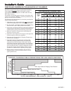
The units are factory charged with the system charge
required when using fifteen (15) feet of rated connecting line.
Unit nameplate charge is the same.
Final refrigerant charge adjustment is necessary. Use
the Subcooling Charging procedure on page 6 or in the
outdoor unit Service Facts.
1. Determine the most practical way to run the lines.
2. Consider types of bends to be made and space limitations.
NOTE:
Large diameter tubing will be very difficult to rebend once it
has been shaped.
3. Determine the best starting point for routing the refriger-
ant tubing — INSIDE OR OUTSIDE THE STRUCTURE.
4. Provide a pull-thru hole of sufficient size to allow both
liquid and gas lines.
5. Be sure the tubing is of sufficient length.
6. Uncoil the tubing — do not kink or dent.
7. Route the tubing making all required bends and properly
secure the tubing before making connections.
8. To prevent a noise within the building structure due to
vibration transmission from the refrigerant lines, the
following precautions should be taken:
a. When the refrigerant lines have to be fastened to floor
joists or other framing in a structure, use isolation
type hangers.
b. Isolation hangers should also be used when refriger-
ant lines are run in stud spaces or enclosed ceilings.
c. Where the refrigerant lines run through a wall or sill,
they should be insulated and isolated.
d. Isolate the lines from all ductwork.
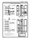
D. SERVICE VALVE OPERATION
BRASS LIQUID AND GAS LINE SERVICE VALVES
The Brass Liquid and Gas Line Service Valves are factory
shipped in the seated position to hold factory charge. The
pressure tap service port (when depressed) opens only to the
field brazing side of the valve when the valve is in the seated
position. The liquid line valve is not a back seating valve
(see WARNING below).
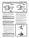
WARNING
!
Extreme caution should be exercised when opening the
Liquid Line Service Valve. Turn valve stem counterclock-
wise only until the stem contacts the rolled edge. (See
Figure 3) No torque is required.
BRASS GAS LINE BALL SERVICE VALVE
The Brass Gas Line Ball Service Valve is shipped in the
closed position to hold the factory refrigerant charge. The
pressure tap service port (when depressed) opens only to the
field brazing side when the valve is in the closed position.
The Gas Line Ball Service Valve is full open with a 1/4 turn.
See Figure 4.
BRAZING REFRIGERANT LINES
1. Remove lower access cover to access service valves.
2. Before brazing, remove plugs from external copper stub
tubes. Clean internal and external surfaces of stub
tubes prior to brazing.
3. Cut and fit tubing, minimizing the use of sharp
90° bends.
4. Insulate the entire gas line and its fittings.
5. Do NOT allow uninsulated liquid line to come in direct
contact with bare gas line.
6. Precautions should be taken to avoid heat damage
to the pressure tap valve core during brazing. It is
recommended that the pressure tap port valve
core be removed and a wet rag wrapped around
the valve body.
NOTE:
Use care to make sure that no moisture enters pressure tap
port, while wet rag is being used.
NOTE:
Precautions should be taken to avoid heat damage to
basepan during brazing. It is recommended to keep the
flame directly off of the basepan.
7. Use a Dry Nitrogen Purge and Brazing Alloy without
flux when brazing the field line to the copper factory
connection. Flow dry nitrogen into either valve pressure
tap port, thru the tubing and out the other port while
brazing.
8. Braze using accepted good brazing techniques.
LEAK CHECK
IMPORTANT:
Replace pressure tap port valve core before attaching hoses for
evacuation.
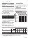
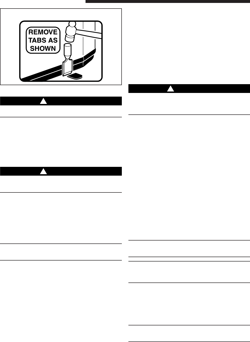
BASEPAN TAB REMOVAL
2