


– 45 –
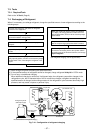
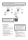
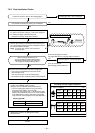
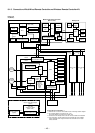
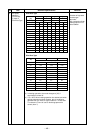
8-1-3. Connection of Both Wired Remote Controller and Wireless Remote Controller Kit
Master wired remote controller
(Max. 2 units)
Weekly timerWireless remote controller kit
TCC-LINK
Central controller
(Option)
TCC-LINK
adapter P.C. board
(MCC-1440)
* Case of TCC-LINK adapter
Case of TCC-LINK adapter
(Option)
Outdoor unit
Outdoor unit
321
321
321
Up to 8 units are connectable. ∗1
∗1 However Max.7 units are connectable in case of mounting network adapter.
∗2 The network adapter is mounted to only 1 unit.
TCC-LINK adapter is mounted to the master unit.
∗3 Connection of the weekly timer to the sub remote controller is unavailable.
∗4 In the left system, set the wireless remote controller side as the follower
remote controller when using the wired remote controller as the master
remote controller.
Same as left
∗2
#3
(Follower)
A B
AB
ABAB
Same as left
∗2
#2
(Follower)
A B
DC5V
DC5V
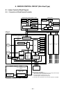
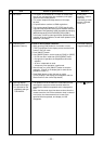
Indoor unit
#1 (Master)
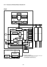
Indoor control P.C. board (MCC-1570)
Drain
pump
Indoor
fan motor
MCU
Driver
Humidifier output
DC12V
DC5V
DC20V
Outside
output
Remote controller
communication circuit
Display
LCD
Function
setup
Key
switch
CN2
CN1
∗3
MCU
Display
LED
Display
LCD
LCD
driver
MCU
Power
circuit
Remote controller
communication circuit
Function
setup
Key
switch
Power circuit
DC280V
Fan motor
control circuit
MCU
EEPROM
TA sensor
TC sensor
TCJ sensor
Float input
HA
Auto grille
panel
TCC-LINK
communication circuit
Run
Warning
Defrost
Thermo. ON
COOL
HEAT
FAN
Serial send/
receive circuit
AC
synchronous
signal input circuit
Power
circuit
Secondary
battery
Outdoor unit
32
1
U3
U4
Remote controller
communication circuit
Receive
circuit
Function setup SW
Grille up/down SW
MCU
Buzzer
Display LED
DC5V
Temporary
operation SW
Power
circuit
Receiver P.C. board
(MCC-1504)