


– 125 –
No.
8
Part name
Compressor
IPDU board
MCC-1596
Procedure
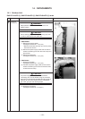
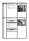
1. Detachment
1) Carry out the operation in 1. of
Q
, 1. of
T
,
1. of
U
, 1. of
V
and 1. of
W
.
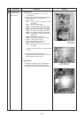
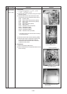
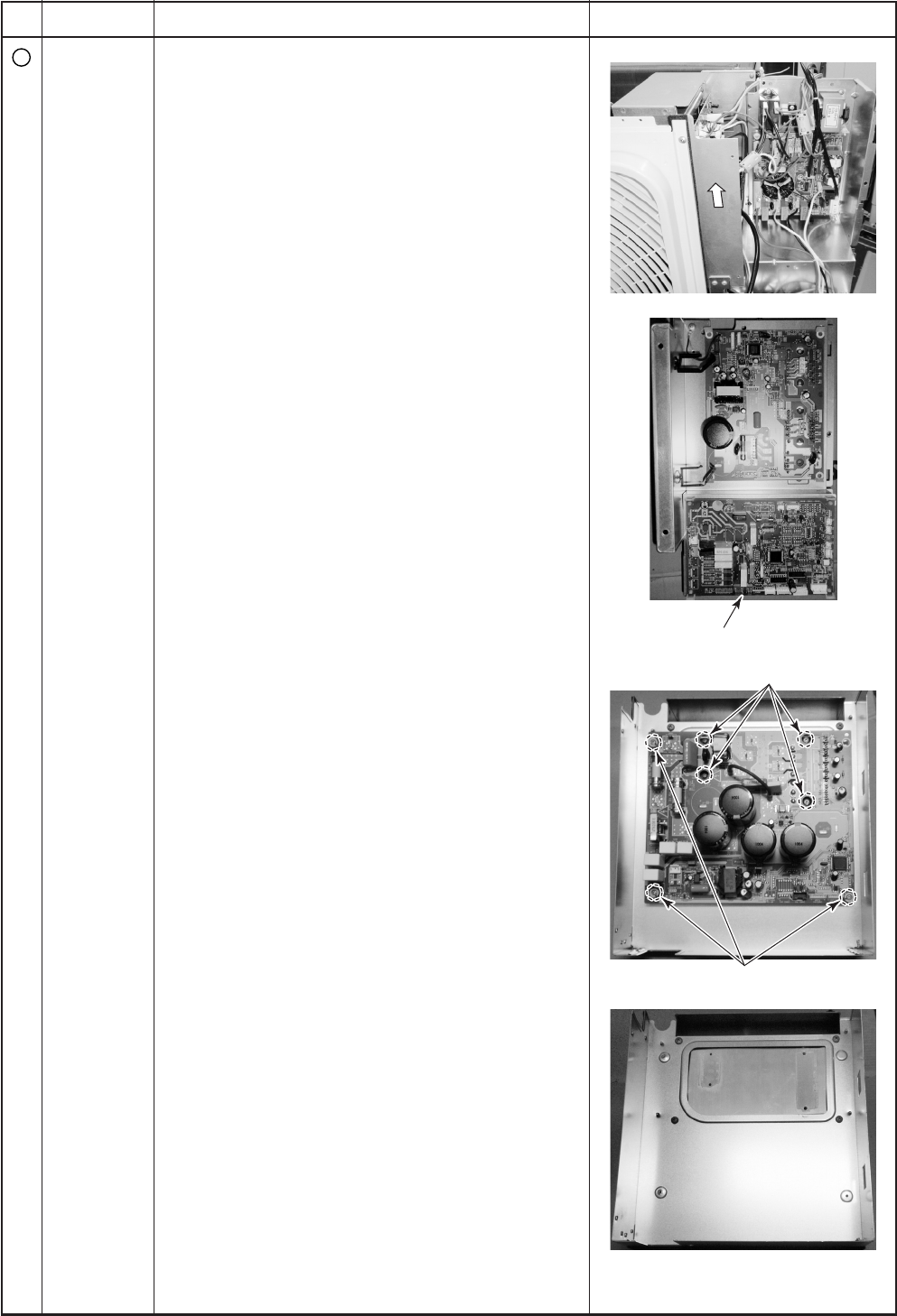
2) Remove the screw (4 positions) fixing the inverter
assembly (IPDU).
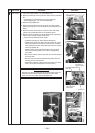
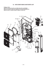
3) Remove the lead wire and connector to other
components from the compressor IPDU board.
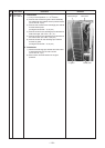
CN04 : Posister (Red)
CN09 : Power supply terminal block (Yellow)
CN10 : Power supply terminal block (Yellow)
CN11 : Relay (Red)
CN12 : Noise filter board (White)
CN13 : Relay (Black)
CN101: FAN-IPDU board (3P, White)
CN211: Compressor (Red)
CN212: Compressor (White)
CN213: Compressor (Black)
CN851: FAN-IPDU board (5P, Red)
∗ Connectors should be removed after unlocking
the housing section.
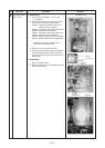
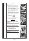
4) Slide and remove the inverter assembly (IPDU).
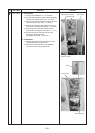
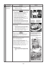
5) Remove the screws (4 positions) fixing the heat
sink and the screws (3 positions) fixing the
compressor IPDU board and then remove the
compressor IPDU board.
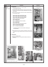
2. Attachment
1) Mount compressor IPDU board.
2) Mount components in the opposite method to that
when removing.
Remarks
Compressor
Compressor
IPDU board
IPDU board
State of compressor IPDU board
when removed
Screws (4 positions)
Screws (3 positions)
Inverter assembly (front)
Compressor
IPDU board