


– 111 –
EN-20 20
Super Digital Inverter
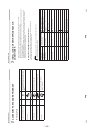
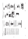
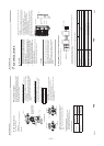
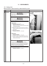
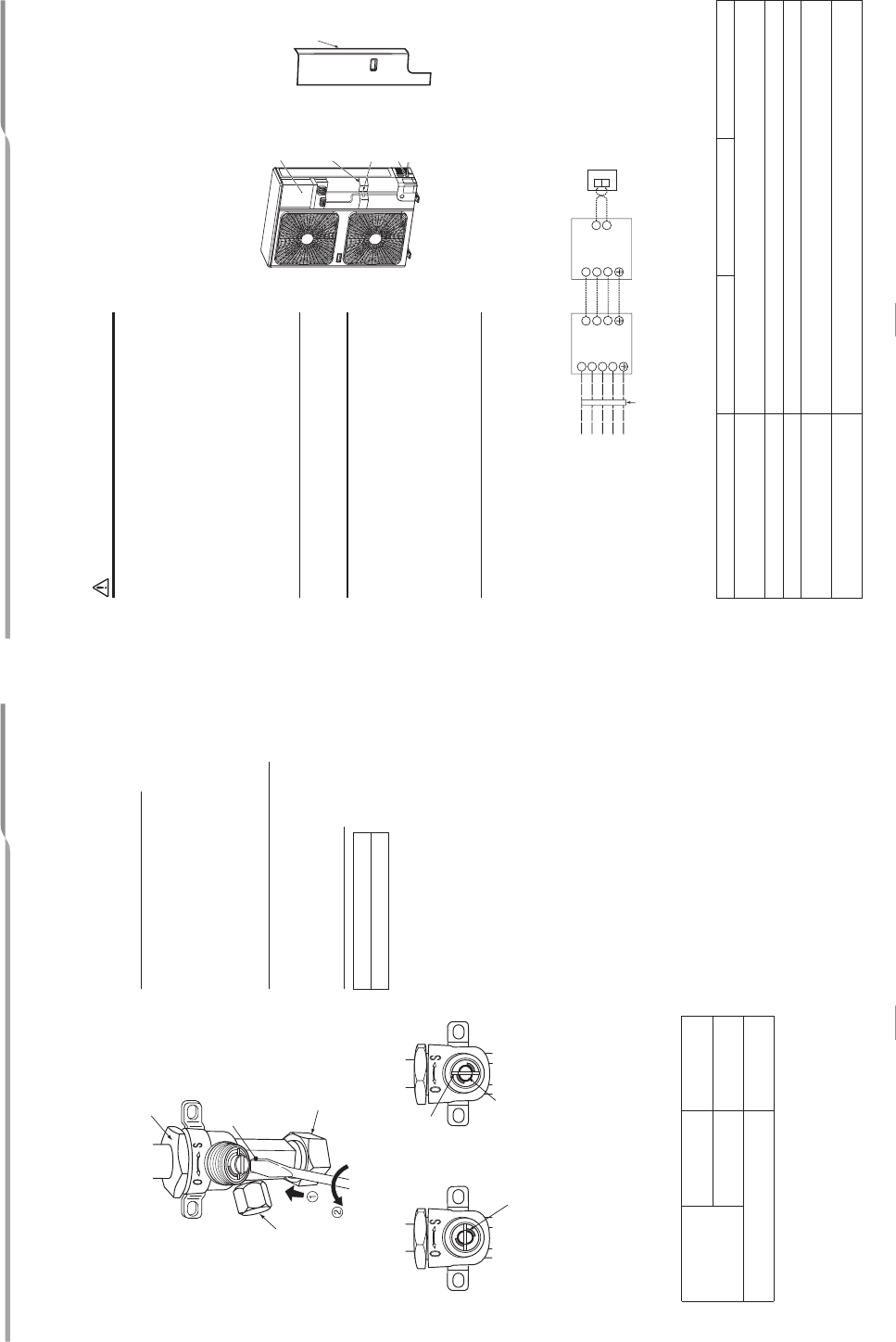
How to open the valve
Open or close the valve.
Liquid side
Open the valve with a 4 mm hexagon wrench.
Gas side
•While the valve is fully opened, after the screwdriver has
reached the stopper, do not apply torque exceeding
5N•m.
Applying excessive torque may damage the
valve.
Valve handling precautions
•Open the valve stem until it strikes the stopper.
It is unnecessary to apply further force.
• Securely tighten the cap with a torque wrench.
Cap t
ightening torque
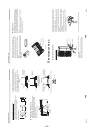
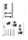
Replenishing refrigerant
This model is a 30 m chargeless type that does not need to
have its refrigerant replenished for refrigerant pipes up to
30 m. When a refrigerant pipe longer than 30 m is used, add
the specified amount of refri
gerant.
Refrigerant replenishing procedure
1. After vacuuming the refrigerant pipe, close the valves
and then charge the refrigerant while the air conditioner
is not working.
2. When the refrigerant cannot be charged to the specified
amount, charge the required
amount of refrigerant from
the charge port of the valve on the gas side during
cooling.
Requirement for replenishing refrigerant
Replenish liquid refrigerant.
When gaseous refrigerant is replenished, the refrigerant
composition varies, which disables normal operation.
Adding additional refrigerant
• L: Pipe length
• To add additional refrigerant to twin and triple systems,
refer to the installation manual supplied with the
branching pipe (sold separately).
• The refrigerant need not be reduced for a 30
meter (or
less) refrigerant pipe.
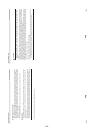
Valve size
Ø9.5 mm
33 to 42 N•m
(3.3 to 4.2 kgf•m)
Ø15.9 mm
20 to 25 N•m
(2.0 to 2.5 kgf•m)
Charge port
14 to 18 N•m
(1.4 to 1.8 kgf•
m)
Valve unit
Charge port
Using a minus screwdriver,
turn it counterclockwise by
90° until it hits the stopper.
(Full open)
Flare nut
Handle position
Closed completely Opened fully
Main stopper
Movable part of valve (Stem)
Stopper pin
31~75 m: L
40g × (L-30
)
21 21-E
N
Super Digital Inverter
7
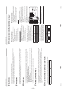
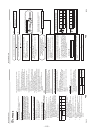
ELECTRICAL WORK
WARNING
1. Using the specified wires, ensure that the wires are
connected, and fix wires securely so that the external
tension to the wires does not affect the connecting
part o
f the terminals.
Incomplete connection or fixation may cause a fire, etc.
2. Be sure to connect the earth wire. (grounding work)
Incomplete grounding may lead to electric shock.
Do not connect ground wires to gas
pipes, water pipes,
lightning rods or ground wires for telephone wires.
3. The appliance shall be installed in accordance with
national wiring regulations.
Capacity shortages of the power circuit or an incomplete
installation may cause an electric shock or fire.
CAUTION
• Wrong wiring may cause a burn-out of some electrical
parts.
•Be sure to use the cord clamps attached to the product.
•Do not damage or scratch the conductive core or inner
insulator of the power and inter-connecting wires when
peeling them.
•Use the power and Inter-connecting wires with specified
thicknesses, specified types and protective devices
required.
• Remove the panel, and you can see electric parts on the
front side.
•A metal pipe can be installed through the hole for wiring.
If the hole size does not fit the wiring pipe to
be used, drill
the hole again to an appropriate size.
•Be sure to clamp the power wires and indoor/outdoor
connecting wires with a banding band along the
connecting pipe so that the wires do not touch
the
compressor or discharge pipe.
(The compressor and the discharge pipe become hot.)
Furthermore, be sure to secure these wires with the pipe
valve fixing plate and cord clamps stored in the electric parts
box.
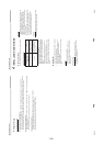
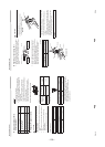
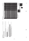
Wi
ring between Indoor Unit and Outdoor Unit
The dashed lines show on-site wiring.
• Connect the indoor/outdoor connectin
g
wi
r
es
to the identical terminal numbers on the terminal block of each unit.
Incorrect connection may cause a failure.
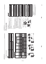
For the air conditioner, connect a power wire with the following specifications.
* Number of
wire wire size
Electric parts box
Pipe valve fixing
plate
Cord clamp
Pipe hole
Panel
2
1
3
2
1
3
N
L2
L3
L1
Outdoor unit
Wired remote controller
Indoor unit
L
eaka
g
e
br
ea
k
er
Input power
380-415 V 3N~, 50Hz
Model (RAV-SP Type)110AT8 140AT8 160AT8
Power supply
380-415 V 3N~
50 Hz
Maximum running current 16.4 A
Recommended field fuse 20 A
Power wire*
5 2.5 mm
2
or more
(H07 RN-F or 60245 IEC 66)
Indoor/outdoor connecting wires*
4
×
×
1.5 mm
2
or more
(H07 RN-F or 60245 IEC 66)