


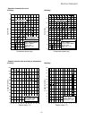
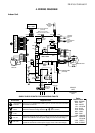
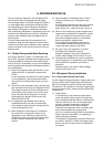
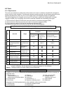
Color
Identification
BRW
RED
WHI
YEL
BLU
BLK
GRY
PNK
ORN
GRN&YEL
GRN
PUR
:
:
:
:
:
:
:
:
:
:
:
:
BROWN
RED
WHITE
YELLOW
BLUE
BLACK
GRAY
PINK
ORANGE
GREEN&
YELLOW
GREEN
PURPLE
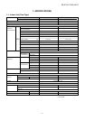
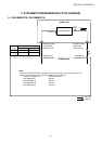
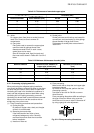
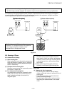
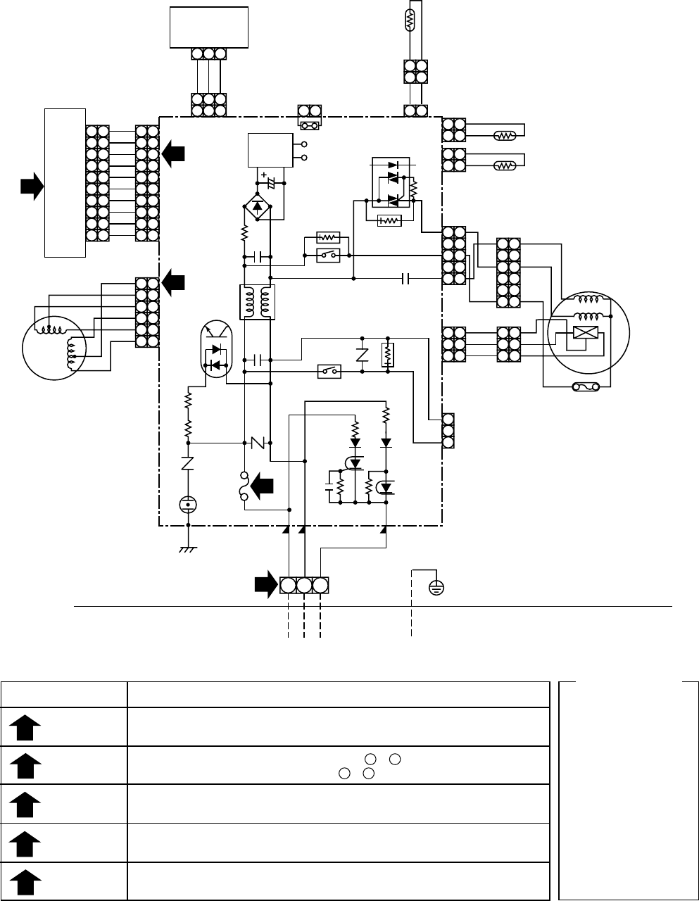
SIMPLE CHECK POINTS FOR DIAGNOSING FAULTS
Diagnosis result
Check to see if OPERATION indicator goes on and off when the main switch
or breaker is turned on.
Check the power supply voltage between 1 - 2 (Refer to the name plate.)
Chack the fluctuate voltage between 2 - 3 (DC15 to 60V)
Check to see if the fuse blows out. (Check the varistor. : R22, R21)
Check the voltage at the No.8 pin on CN13 connector of the infrared receiver.
(Check the transformer and the power supply circuit of the rated voltage.)
Check the voltage at the brown lead of the louver motor.
(Check the transformer and the power supply circuit of the rated voltage.)
Check items
OPERATION
indicator
Terminal
block
Fuse
6.3A
DC 5V
DC 12V
1
2
3
4
5
1
2
21
3
4
5
6
7
8
9
10
1
2
3
4
5
6
7
8
9
10
1
2
3
4
5
6
7
8
9
10
1
2
3
4
5
6
7
8
9
10
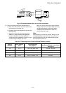
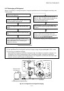
INFRARED RAYS RECEIVE
AND INDICATION PARTS
SWITCH PCB
MCC-1428B
BRW
RED
ORN
YEL
PNK
BLU
BLU
WHI
BLU
BLU
BLU
BLU
BLU
BLU
BLU
BLU
CN13
CN07
CN100
CN402
J401
C01
R01
DB01
C02
DC12V
IC03
C501
R405
R21
R22
SG01
F01
T6.3A
FUSE
250VAC
R09
R507
CR401
RY401
R506
CR502
RY501
CR501
CN05
CN03
CN01
CN10
CN11
CN401
CN23
FOR FLOAT SWITCH
(OPTION)
When you use float
switch you should cut J401
HEAT
EXCHANGER
SENSOR
(TCJ)
THERMO
SENSOR
(TA)
HEAT
EXCHANGER
SENSOR
(TC)
CN101
CN25
1
2
4
5
3
3
21 3
21 3
21
3
WHI
GRY
GRY
WHI
RED
WHI
RED
BLK
BLK
BLK
BLK
BLK
BLK
BLK
BLK
CN30
P04
CN31
WHI
RED
BRW
POWER
SUPPLY
CIRCUIT
C15
IC04
DC5V
5
4
3
2
1
5
4
3
2
1
5
4
3
2
1
5
4
3
2
1
1
2
3
1
2
3
1
2
3
1
2
3
1
2
3
66
5
4
3
2
1
5
4
3
2
1
66
GRY
YEL
BLU
PUR
GRY
100”C
FAN-MOTOR
FOR DRAIN PUMP
(OPTION)
MCC-1428A
INDOOR
UNIT
LOUVER
MOTOR
OUTDOOR
UNIT
GRN&YEL
INDOOR
TERMINAL
BLOCK
1
2
1
2
1
2
1
2
21
21
21
21
4. WIRING DIAGRAM
Indoor Unit
– 5 –
FILE NO. SVM-06012