


– 137 –
No.
U
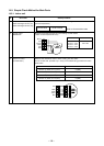
Part name
Control P.C.
board
Procedure
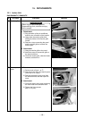
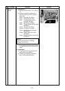
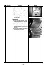
1. Detachment
1) Perform works of items 1 of Q and 1 of
R.
2) Remove connectors which are con-
nected from the control P.C. board to
other parts.
CN33 : Flap motor (5P: White)
CN34 : Float switch (3P: Red)
CN41 : Terminal block of remote
controller (3P: Blue)
CN68 : Drain pump (3P: Blue)
CN67 : Terminal block of power supply
(5P: Black)
CN101 : TC sensor (2P: Black)
CN102 : TCJ sensor (2P: Red)
CN104 : Room temperature sensor
(2P: Yellow)
CN333 : Power supply of fan motor
(5P: White)
CN334 : Position detection of fan motor
(5P: White)
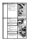
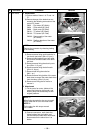
NOTE :
Remove the connector by releasing
locking of the housing.
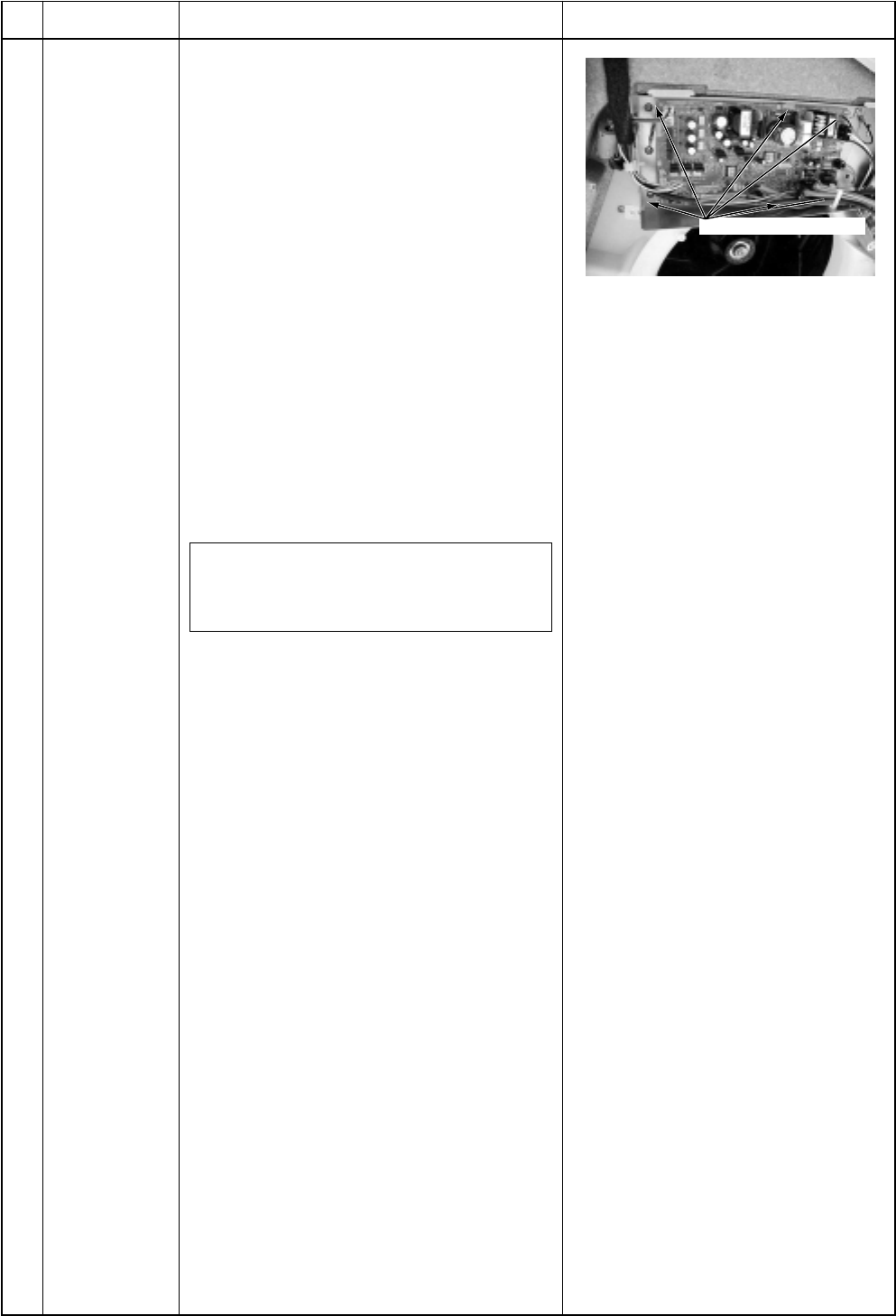
3) Unlock locking of the card-edge spacer
at 6 positions to remove the control P.C.
board.
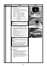
2. Attachment
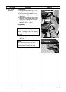
1) Fix the control P.C. board to the card-
edge spacer at 6 positions.
2) Connect the connectors removed in
item 1 to the original positions.
Remarks
Card-edge spacer