


Appendix
Appendix-4
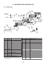
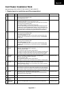
4. Cord heater installation work procedure
No. Photo / Explanatory diagram Procedure
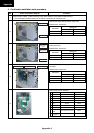
1
Remove each cabinet, inverter assembly, motor base assembly, and partition board assembly.
* Do not damage the electric parts such as cables, connectors, etc. while this work.
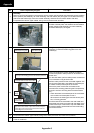
Remove the upper cabinet and the valve cover.
Related parts / Screws list
Used screw
Part name
Screw type Quantity
Upper cabinet Ø4 × 8 5
Valve cover Ø4 × 1 1
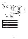
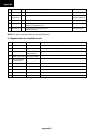
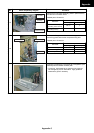
1-1
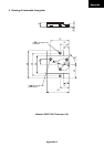
Remove the front cabinet, the wiring cover and the
water-proof cover.
Related parts / Screws list
Used screw
Part name
Screw type Quantity
Front cabinet Ø4 × 8 7
Wiring cover Ø4 × 8 2
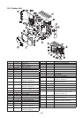
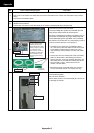
1-2
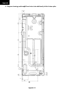
Remove the side cabinet (R/L) and the inverter
assembly.
Related parts / Screws list
Used screw
Part name
Screw type Quantity
Side cabinet (R) Ø4 × 8 7
Side cabinet (L) Ø4 × 8 3
Inverter assembly Ø4 × 8 1
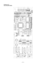
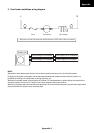
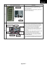
1-3
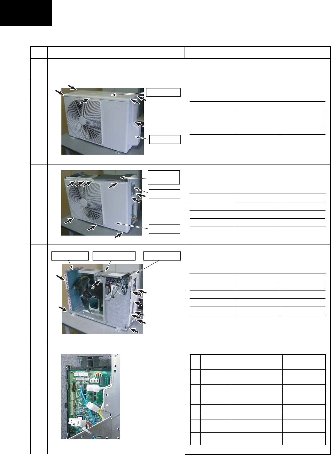
Remove the inverter assembly.
No. Part name Connector No. Connector color
1 TE sensor CN600 White
2 TD sensor CN601 White
3 TO sensor CN602 White
4 TS sensor CN603 White
5
4-way valve
coil
CN701 Yellow
6 PMV coil CN700 White
7 Fan motor CN300 White
8
Compressor
lead
(Intermediate connector)
White
9
Reactor
(2 pieces.)
(Intermediate connector)
White
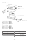
1-4
Upper cabinet
Valve cover
Wiring cover
Water-proof
cover
Front cabinet
Side cabinet (L) Side cabinet (R)Inverter assembly