


– 98 –
No.
11
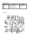
Part name Procedure Remarks
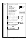
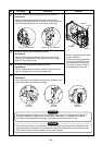
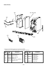
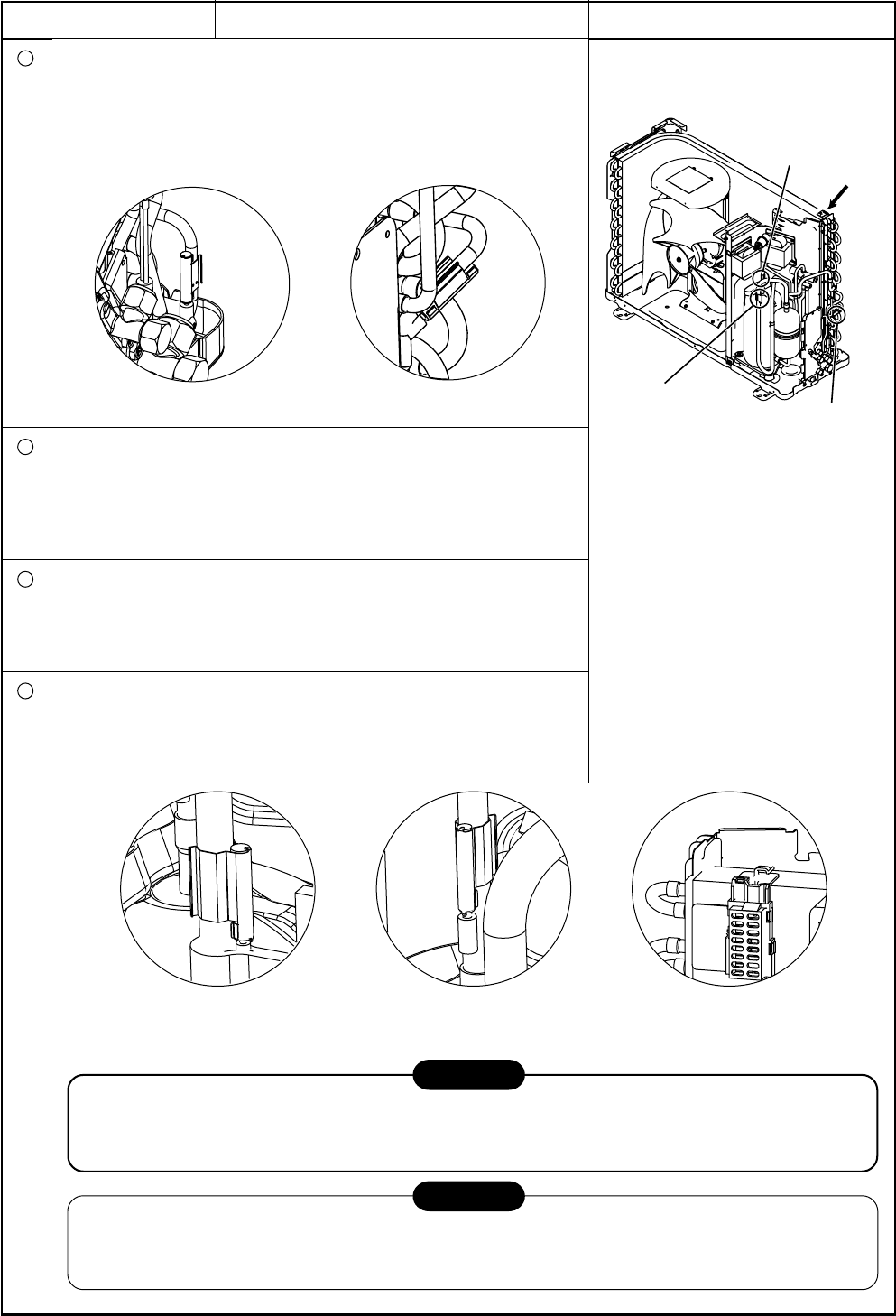
TE sensor (outdoor heat exchanging temperature sensor)
• Attachment
With the leads pointing downward and the sensor leads
pointing in the direction shown in the figure, install the sensor
onto the straight pipe part of the condenser output pipe.
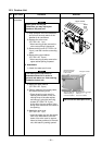
CAUTION
During the installation work (and on its completion), take care not to damage the coverings of
the sensor leads on the edges of the metal plates or other parts. It is dangerous for these
coverings to be damaged since damage may cause electric shocks and/or a fire.
CAUTION
After replacing the parts, check whether the positions where the sensors were installed are the
proper positions as instructed. The product will not be controlled properly and trouble will result
if the sensors have not been installed in their proper positions.
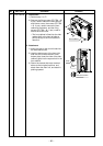
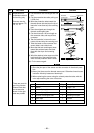
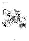
Detail B
Detail A
Arrow D
Detail C
• Shown in the above figure is the
model 13GAVP-E.
• The sensor mounting positions
in the model 10GAVP-E are all
the same with the sole excep-
tion of the TE sensor. Refer to
the figure shown on the left.
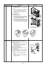
Detail C for 13, 16GAVP-E
Detail C for 10GAVP-E
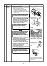
TS sensor (Suction pipe temperature sensor)
• Attachment
With its leads pointing downward, point the sensor in the
direction of the packed valve, and install it onto the straight
pipe part of the suction pipe.
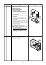
TD sensor (Discharge pipe temperature sensor)
• Attachment
With its leads pointed downward, install the sensor onto the
vertical straight pipe part of the discharge pipe.
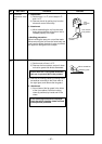
TO sensor (Outside air temperature sensor)
• Attachment
Insert the outdoor air temperature sensor into the holder, and
install the holder onto the heat exchanger.
Detail B
TS sensor
Detail A
TD sensor
Arrow D
TO sensor
12
13
14