


– 44 –
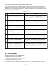
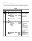
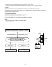
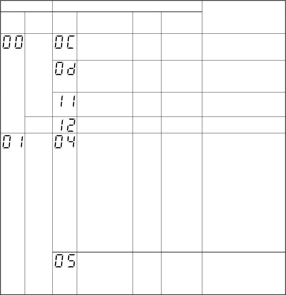
Block distinction Operation of diagnosis function
Check
code
Block
Check
code
Cause of operation
Air
conditioner
status
Remarks
Judgment and action
Short-circuit or
disconnection of the room
temperature sensor
(TA sensor).
Operation
continues.
Displayed when
error is detected.
1. Check the room temp. sensor.
2. When the room temp. sensor is
normal, check P.C. board.
Being out of place,
disconnection, short-
circuit, or migration of
heat exchanger sensor
(TC sensor)
Operation
continues.
Displayed when
error is detected.
1. Check heat exchanger sensor.
2. When heat exchanger sensor is
normal, check P.C. board.
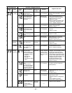
Indoor P.C.
board etc.
Lock of indoor fan or
trouble on the indoor fan
circuit
All off Displayed when
error is detected.
1. Check P.C. board.
2. When P.C. board is normal, check
the motor.
Not
displayed
Trouble on other indoor
P.C. boards
Operation
continues.
Displayed when
error is detected.
Replace P.C. board.
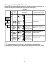
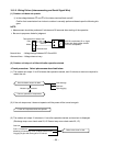
Return serial signal is not
sent to indoor side from
operation started.
(1) Defective wiring of
connecting cable
(2) Operation of
compressor thermo.
Gas shortage
Gas leak
Operation
continues.
Flashes when
trouble is detected
on Return serial
signal, and normal
status when signal
is reset.
1. When the outdoor unit never
operate:
(1) Check connecting cable, and
correct if defective wiring.
(2) Check 25A fuse of inverter P.C.
board.
(3) Check 3,15A of inverter P.C.
board.
2. To display [Other] block during
operation, check compressor
thermo. operation and supply gas
(check gas leak also).
3. Unit operates normally during check.
If Return serial signal does not stop
between indoor terminal board 2 and
3, replace inverter P.C. board.
If signal stops between indoor
terminal board 2 and 3, replace
indoor P.C. board.
Connecting
cable and
serial signal
Operation command
signal is not sent to
outdoor side.
Operation
continues
Flashes when
trouble is detected
on Operation
command signal,
and normal status
when signal is
reset.
If Return serial signal does not stop
between indoor terminal board 2 and 3,
replace inverter P.C. board.
If signal stops between indoor terminal
board 2 and 3, replace indoor P.C.
board.
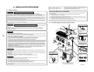
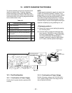
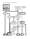
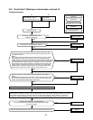
10-4-3. Caution at Servicing
(1) After servicing, push the START/STOP button to return to the normal mode.
(2) After servicing by the check code, turn off breaker of the power supply, and turn on breaker of the power
supply again so that memory in the microcomputer returns the initial status. However, the check codes are
not deleted even if the power supply is turned off because they are stored in the fixed memory.
Table 10-4-1