


– 37 –
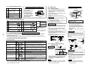
• Secure the outdoor unit with the fixing bolts and nuts if the
unit is likely to be exposed
to a strong wind.
• Use ø8 mm or ø10 mm
anchor bolts and nuts.
• If it is necessary to drain
the defrost water attach
drain nipple to the bottom
plate of the outdoor unit
before installing it.
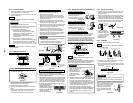
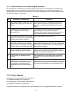
9-1-4. Installation/Servicing Tools Changes in the product and components
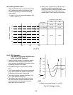
In the case of an air conditioner using R410A, in order to prevent any other refrigerant from being charged
accidentally, to service port diameter of the outdoor unit control valve (3 way valve) has been changed.
(1/2 UNF 20 threads per inch)
• In order to increase the pressure resisting strength of the refrigerant piping flare processing diameter and
size of opposite side of flare nuts has been changed.
(for copper pipes with nominal dimensions 1/2 and 5/8)
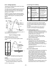
New tools for R410A
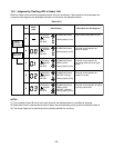
9-1-2. Optional Installation Parts
9-1-3. Accessory and Installation Parts
Fixing bolt arrangement of outdoor unit
Part
Parts name Q’ty
code
Refrigerant piping
Each
A Liquid side : Ø6,35
one
Gas side : Ø9,52
B
Pipe insulating material
1
(Polyethylene foam, 6mm thick)
C Putty, PVC tapes
Each
one
Changes
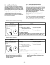
As pressure is high, it is impossible to measure by means of
conventional gauge. In order to prevent any other refrigerant from
being charged, each port diameter has been changed.
In order to increase pressure resisting strength, hose materials and
port size have been changed (to 1/2 UNF 20 threads per inch).
When purchasing a charge hose, be sure to confirm the port size.
As pressure is high and gasification speed is fast, it is difficult to read
the indicated value by means of charging cylinder, as air bubbles
occur.
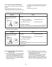
The size of opposite sides of flare nuts have been increased. Incidentally,
a common wrench is used for nominal diameters 1/4 and 3/8.
By increasing the clamp bar’s receiving hole, strength of spring in the
tool has been improved.
Used when flare is made by using conventional flare tool.
Connected to conventional vacuum pump. It is necessary to use an
adapter to prevent vacuum pump oil from flowing back to the charge
hose. The charge hose connecting part has two ports-one for
conventional refrigerant (7/16 UNF 20 threads per inch) and one for
R410A. If the vacuum pump oil (mineral) mixes with R410A a sludge
may occur and damage the equipment.
Exclusive for HFC refrigerant.
Exclusive for HFC refrigerant.
New tools for R410A
Gauge manifold
Charge hose
Electronic balance
for refrigerant charging
Torque wrench
(nominal diam. 1/2, 5/8)
Flare tool (clutch type)
Gauge for projection adjustment
Vacuum pump adapter
Gas leakage detector
600
115
Suction side
Diffuser
310
76
Drain hole
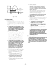
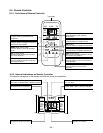
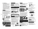
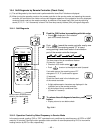
9-2. Indoor Unit
9-2-1. Installation Place
• A place which provides the spaces around the
indoor unit as shown in the above diagram.
• A place where there is no obstacle near the air
inlet and outlet.
• A place which allows an easy installation of the
piping to the outdoor unit.
• A place which allows the front panel to be
opened.
CAUTION
• Direct sunlight to the indoor unit wireless
receiver should be avoided.
• The microprocessor in the indoor unit should not
be too close to r-f noise sources.
(For details, see the owner's manual.)
Remote controller
• A place where there are no obstacles such as a
curtain that may block the signal from the indoor
unit.
• Do not install the remote controller in a place
exposed to direct sunlight or close to a heating
source, such as a stove.
• Keep the remote controller at least 1 m apart from
the nearest TV set or stereo equipment.
(This is necessary to prevent image disturbances
or noise interference.)
• The location of the remote controller should be
determined as shown below.
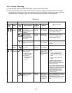
Indoor unit
Pipe
hole
65,5mm
120mm
Thread
Weight
1
Installation
plate
5
Mounting
screw
Pipe hole
65,5mm
40mm
Anchor bolt hole
66mm
(Top view)
Indoor unit
5m
5m
4
5
˚
45˚
Remote
controller
Reception
range
*
: Axial distance
Remote
controller
Reception
range
7m
Indoor unit
(Side view)
*
7m
75˚
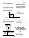
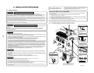
The center of the piping slot
is above the arrow.
The center of the pipe
hole is above the arrow.
80mm
Pipe hole
65mm
40,5
mm
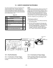
Fig. 9-2-2
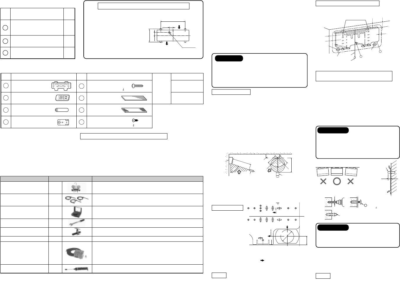
1. After determining the pipe hole position on the
mounting plate (80 mm
), drill the pipe hole
(ø65 mm) at a slight downward slant to the
outdoor side.
NOTE
• When drilling the wall that contains a metal lath,
wire lath or metal plate, be sure to use a pipe
hole brim ring sold separately.
Anchor bolt
Projection
15mm or less
5 mm dia. hole
Clip anchor
(local parts)
5 Mounting screw
Ø4 x 25
Fig. 9-2-3
When the installation plate is directly
mounted on the wall
1. Securely fit the installation plate onto the
wall by screwing it in the upper and lower
parts to hook up the indoor unit.
2. To mount the installation plate on a
concrete wall with anchor bolts, utilize the
anchor bolt holes as illustrated in the
above figure.
3. Install the installation plate horizontally in
the wall.
CAUTION
When installing the installation plate with
mounting screw, do not use the anchor
bolt hole. Otherwise the unit may fall down
and result in personal injury and property
damage.
Fig. 9-2-1
9-2-2. Cutting a Hole and Mounting
Installation Plate
Cutting a Hole
When install the
refrigerant pipes
from the rear.
Fig. 9-2-5
Mounting the Installation Plate
For installation of the indoor unit, use the
paper pattern on the back.
Fig. 9-1-2
Applicable to R22 model
××
××
×
××
××
×
¡
××
××
×
¡
——
¡
××
××
×
• Incidentally, the “refrigerant cylinder” comes with the refrigerant designation (R410A) and protector coating
in the U. S’s ARI specified rose color (ARI color code: PMS 507).
• Also, the “charge port and packing for refrigerant cylinder” require 1/2 UNF 20 threads per inch correspond-
ing to the charge hose’s port size.
Fig. 9-2-4
Deodorizing filter x 1
Part
No.
Part name (Q'ty)
Part
No.
Part name (Q'ty)
Installation plate x 1
Wireless remote controller x 1
Remote controller holder x 1
Battery x 2
Pan head wood screw Ø3,1x 16
x 2
Mounting screw Ø4 x 25
x 6
Purifying filter x 1
1
2
3
4
5
6
7
8
Name
Owner’s manual
Installation manual
Others
This model is not equipped with
an extention drain hose.
Option :
For the extention drain hose, use
an optionally available RB-821SW
or commercially available one.
CAUTION
Failure to firmly install the unit may result
in personal injury and property damage if
the unit falls.
• In case of block, brick, concrete or similar
type walls, make 5 mm dia. holes in the
wall.
• Insert clip anchors for appropriate
U
mounting screws.
NOTE
• Install the installation plate using 4 to 6
pieces of mounting screw securing four
corners with screws.