


– 40 –
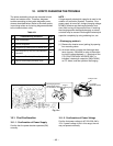
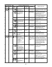
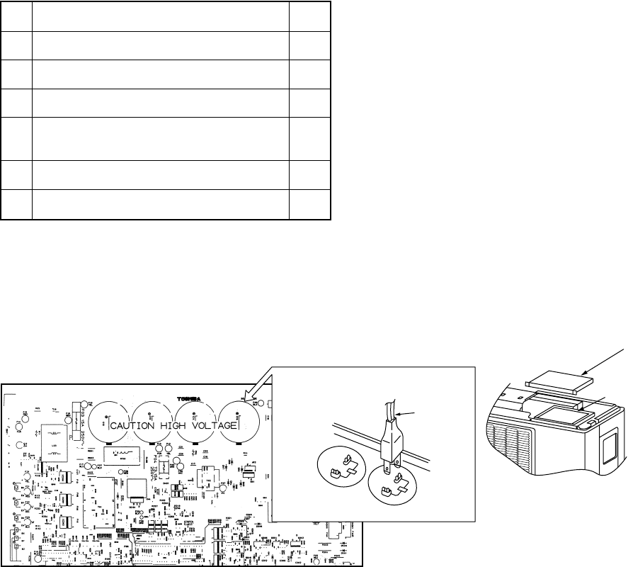
Discharging position
(Discharging period
10 seconds or more)
Plug of
soldering iron
Inverter cover
P. C. board
(Soldered surface)
MCC-808
10. HOW TO DIAGNOSE THE TROUBLE
The pulse modulating circuits are mounted to both
indoor and outdoor units. Therefore, diagnose
troubles according to the trouble diagnosis proce-
dure as described below. (Refer to the check points
in servicing written on the wiring diagrams attached
to the indoor/outdoor units.)
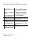
Table 10-1
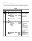
No. Troubleshooting Procedure Page
1 First Confirmation 40
2 Primary Judgment 41
3 Judgment by Flashing LED of Indoor Unit 42
4
Self-Diagnosis by Service Check Remote
43
Controller
5 Judgment of Trouble by Every Symptom 46
6 How to Check Simply the Main Parts 53
NOTE :
A large-capacity electrolytic capacitor is used in the
outdoor unit controller (inverter). Therefore, if the
power supply is turned off, charge (charging voltage
DC280V) remains and discharging takes a lot of
time. After turning off the power source, if touching
the charging section before discharging, an electri-
cal shock may be caused. Discharge the electrolytic
capacitor completely by using soldering iron, etc.
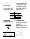
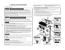
< Discharging method >
(1) Remove the inverter cover (plating) by opening
four mounting claws.
(2) As shown below, connect the discharge resis-
tance (approx. 100Ω40W) or plug of the solder-
ing iron to voltage between + – terminals of the
C14 (“CAUTION HIGH VOLTAGE 320V” is
indicated.) electrolytic capacitor (500µF/400V)
on P.C. board, and then perform discharging.
Fig. 10-1
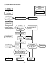
10-1. First Confirmation
10-1-1. Confirmation of Power Supply
Confirm that the power breaker operates (ON)
normally.
10-1-2. Confirmation of Power Voltage
Confirm that power voltage is AC 220–230–240 ±
10%. If power voltage is not in this range, the unit
may not operate normally.