


FILE NO. SVM-03008
– 78 –
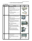
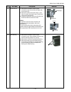
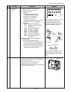
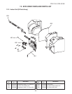
1) Disconnect lead wires and connectors
connected from the control board
assembly to other parts.
1. Lead wires
• Connection with terminal block :
3 wires (Black, White, Orange)
• Connection with compressor :
Remove the connector (3P)
• Connection with reactor :
Remove the relay connectors from P07, 08
(2P, White) and P12, 13 (2P, Yellow).
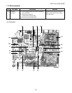
2. Connectors
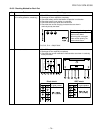
CN300 : Outdoor fan (3P, White)
CN301 : Outdoor fan position detection
(5P, White)
CN701 : 4-way valve (3P, Yellow)
CN600 : TE sensor (2P, White)
CN601 : TD sensor (3P, White)
CN603 : TS sensor (3P, White)
CN602 : TO sensor (2P, White)
CN500 : Case thermo. (2P, White)
CN703 : Pulse modulating valve
(6P, White)
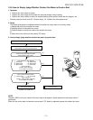
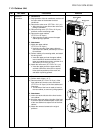
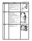
2) Remove the control board assembly from
P.C. board base.
1. Main control board assembly side
• Remove two claws of P.C. board base, and
remove upward the heat sink with hands.
• Remove three screws fixing the heat sink
and main control board assembly side, and
replace the board with a new one.
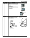
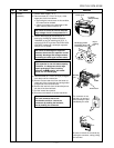
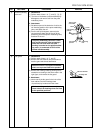
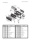
1) Perform work of item 1 of 1, 1 and 2, 3.
2) Remove fixed screws fixing to the bottom plate.
(ST1T∅4 x 10s 3 pcs.)
3) Remove fixed screws fixing to the heat
exchanger. (ST1T∅4 x 10s 2 pcs.)
4) Remove fixed screw fixing to the valve mounting
plate. (ST1T∅4 x 10s 1 pc.)
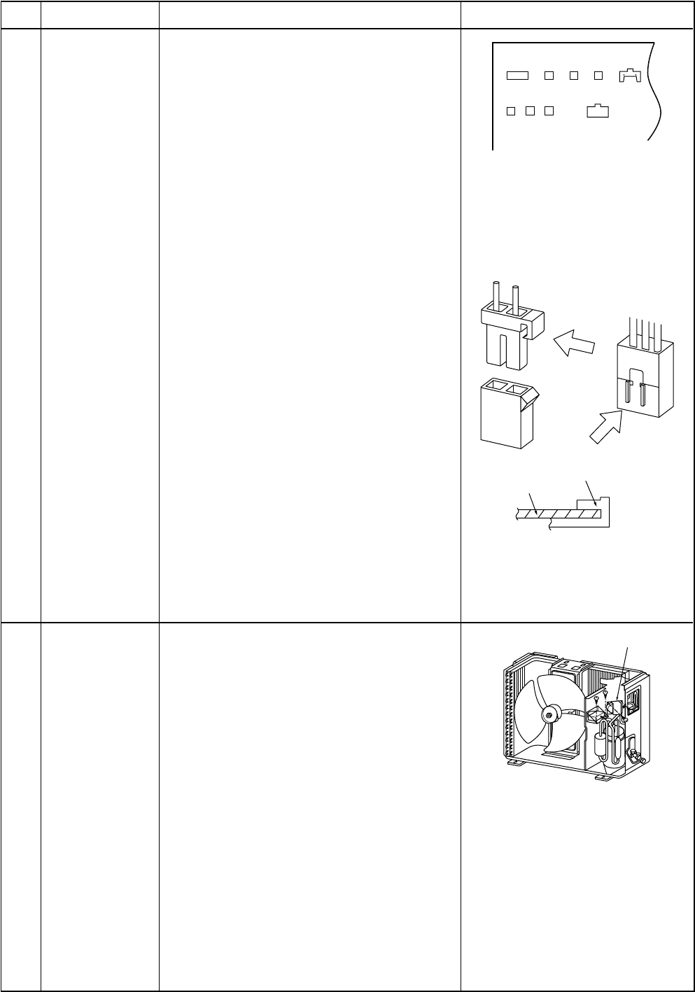
4 Control board
assembly
5 Rear cabinet
CN300, CN301 and CN701, etc. at the
control board assembly side are
connectors with locks. Therefore,
remove the connector while pushing
the part indicated by an arrow.
No. Part name Procedures Remarks
CN701
CN500
CN703 CN602 CN301
CN300
CN603
CN601 CN600
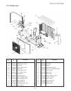
P.C. board base
P.C. board
When mounting a new board, check
that the board is correctly set in the
groove of base holder of P.C. board
base.
Reactor