


– 18 –
FILE NO. SVM-03008
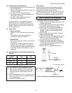
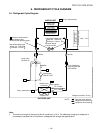
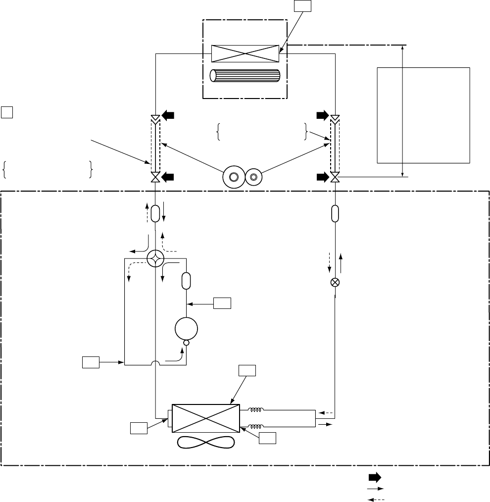
6. REFRIGERANT CYCLE DIAGRAM
6-1. Refrigerant Cycle Diagram
Note :
• The maximum length of the pipe for this air conditioner is 15 m. The additional charging of refrigerant is
unnecessary because this air conditioner is designed with charge-less specification.
Deoxidized copper pipe
NOTE :
Gas leak check position
Refrigerant flow (Cooling)
Refrigerant flow (Heating)
INDOOR UNIT
T1
TO
Temp. measurement
Indoor heat
exchanger
Cross flow fan
Deoxidized copper pipe
Outer dia. : 6.35 mm
Thickness : 0.8 mm
Sectional shape
of heat insulator
Allowable height
difference : 10m
Allowable pipe length
Max. : 15 m
P
Pressure measurement
Gauge attaching port
Vacuum pump connecting port
Strainer
Pulse modulating
valve at liquid side
(SEV16RC3)
∅1.5 x 200
s
∅1.5 x 200
s
TD
4-way valve
(CHV-0213)
Compressor
DA91A1F-45F
TS
T2
Outdoor heat
exchanger
Split capillary
Temp. measurement
Propeller fan
Refrigerant amount : 0.9 kg
OUTDOOR UNIT
Muffler
Muffler
TE
Outer dia. : 9.52 mm
Thickness : 0.8 mm