– 63 –
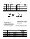
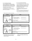
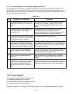
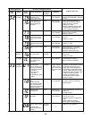
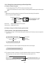
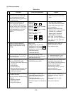
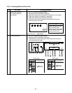
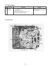
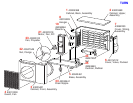
Remarks
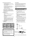
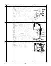
The connector is one with lock,
so remove it while pushing the
part indicated by an arrow.
Be sure to remove the connector
by holding the connector, not by
pulling the lead wire.
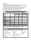
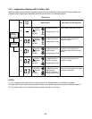
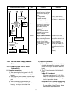
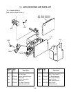
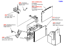
No. Part name
S
Inverter
assembly
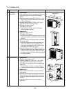
Procedure
1. Detachment
1) Perform work of item 1 of
Q
.
2) Remove screw (ST1TØ4 x 10l 1 pc.) of the
upper part of the front cabinet.
• If removing the inverter cover in this condition,
P.C. board can be checked.
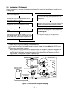
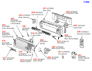
• If there is no space in the upper part of the
upper cabinet, perform work of
R
.
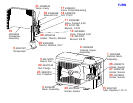
Be careful to check the inverter because
high-voltage circuit is incorporated in it.
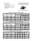
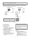
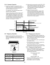
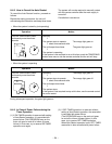
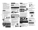
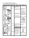
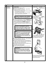
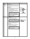
3) Perform discharging by connecting + , – polarity
by discharging resistance (approx. 100Ω40W) or
plug of soldering iron to + , – terminals of the
C14 (printed “CAUTION HIGH VOLTAGE” is
attached.) electrolytic capacitor (500µF) on P.C.
board.
Be careful to discharge the capacitor
because the electrolytic capacitor cannot
naturally discharge and voltage remains
according to trouble type in some cases.
NOTE :
This capacitor is one with mass capacity.
Therefore, it is dangerous that a large
spark generates if short-circuiting be-
tween + , – polarity with screwdriver, etc.
for discharging.
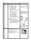
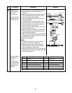
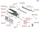
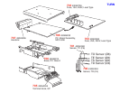
4) Remove screw (ST1TØ4 x 10l 1 pc.) fixing the
main body and the inverter box.
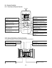
5) Remove various lead wires from the holder at
upper part of the inverter box and wiring holder
at right side of the terminal block.
6) Remove the lead wire from the bundled part at
left side of the terminal block.
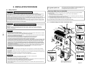
7) Pull the inverter box upward.
8) Disconnect connectors of various lead wires.
Requirement :
As each connector has a lock mecha-
nism, avoid to remove the connector by
holding the lead wire, but by holding the
connector.
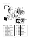
Terminal block
Inverter cover
P. C. board
(Soldered surface)
Discharging position
(Discharging period
10 seconds or more)
Plug of
soldering
iron
Bundled
part
Holder