


– 62 –
Procedure
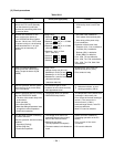
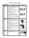
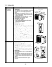
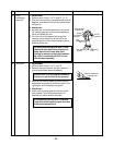
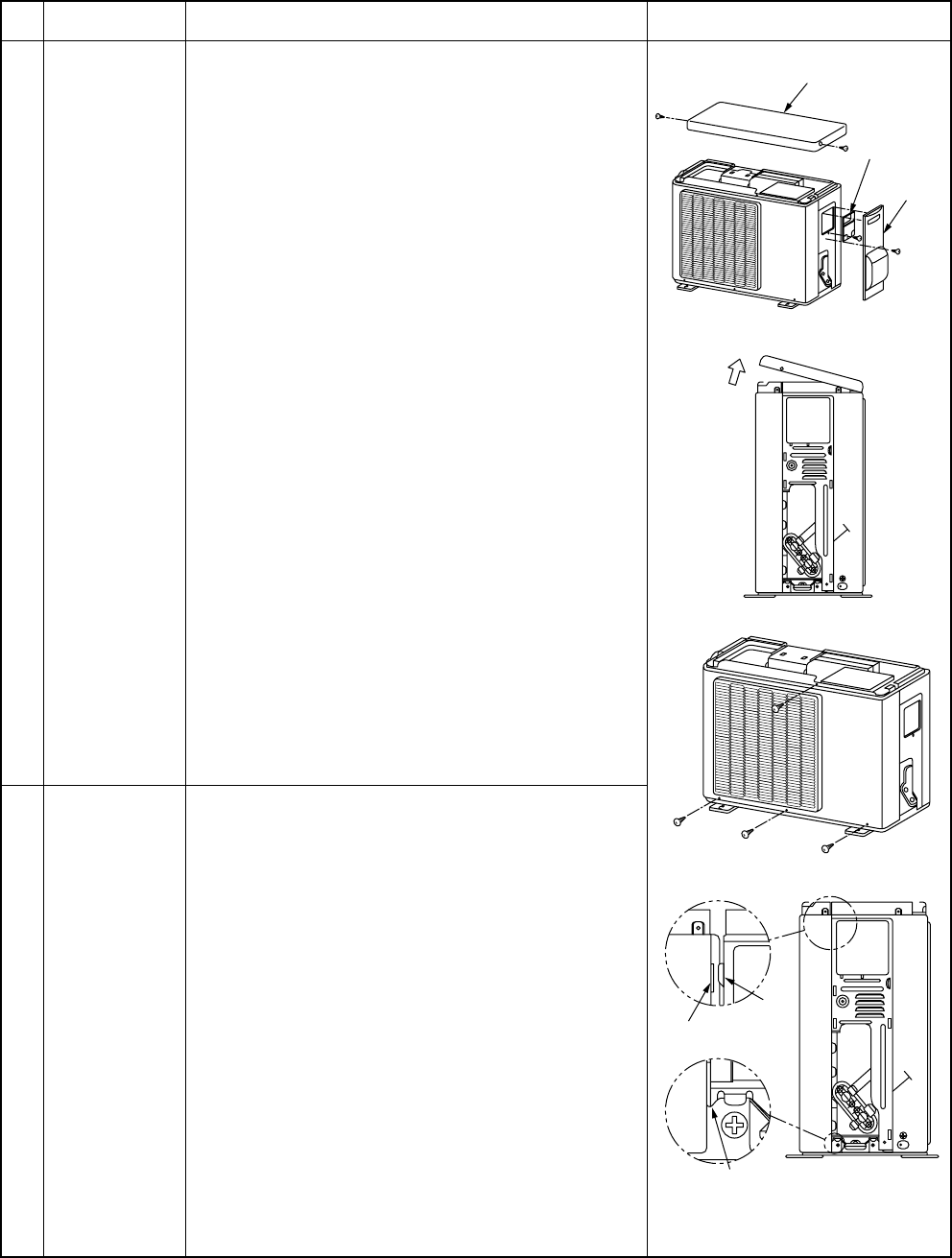
1. Detachment
1) Stop operation of the air conditioner, and remove
the power plug of the indoor unit from plug
socket.
2) Remove the valve cover. (ST1TØ4 x 10l 1 pc.)
• After removing screw, remove the valve cover
pulling it downward.
3) Remove wiring cover (ST1TØ4 x 10l 2 pcs.),
and then remove connecting cable.
4) Remove the upper cabinet.
(ST1TØ4 x 10l 2 pcs.)
• After removing screws, remove the upper
cabinet pulling it upward.
2. Attachment
1) Attach the upper cabinet.
(ST1TØ4 x 10l 2 pcs.)
• Hook the rear side of the upper cabinet to claw
of the rear cabinet, and then put it on the front
cabinet.
2) Perform cabling of connecting cable, and attach
the wiring cover.
• Insert the upper part into the upper cabinet,
insert claw which has been hooked to the
lower part into the square hole, and then fix it
with screw. (ST1TØ4 x 10l 1 pc.)
3) Attach the valve cover. (ST1TØ4 x 10l 1 pc.)
• Insert the upper part to the upper cabinet, set
hook claw of the valve cover to square holes
(at three positions) of the main unit, and attach
it pushing upward.
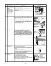
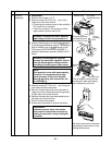
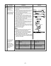
1. Detachment
1) Perform work of item 1 of
Q
.
2) Remove screws (ST1TØ4 x 10l 1 pc.) of the
front cabinet and inverter cover and screws
(ST1TØ4 x 10l 3 pcs.) of the front cabinet and
lower part.
• The left side of the front is made to insert to
the rear cabinet, so remove it pulling upward.
2. Attachment
1) Insert claw at the left side of the front into the
rear cabinet.
2) Hook the lower part at the right side of the front
to concave part of the bottom plate. Insert claw
of the rear cabinet into square hole of the front
cabinet.
3) Attach the removed screws to the original
positions.
No. Part name
Q
Common
procedure
R
Front cabinet
Remarks
Upper cabinet
Wiring
cover
Valve
cover
Square hole
Claw
Concave section
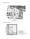
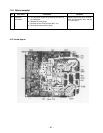
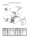
11-3. Outdoor Unit