


– 82 –
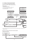
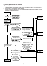
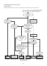
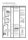
11-8. How to Diagnose Trouble in Outdoor Unit
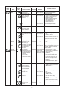
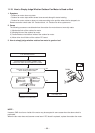
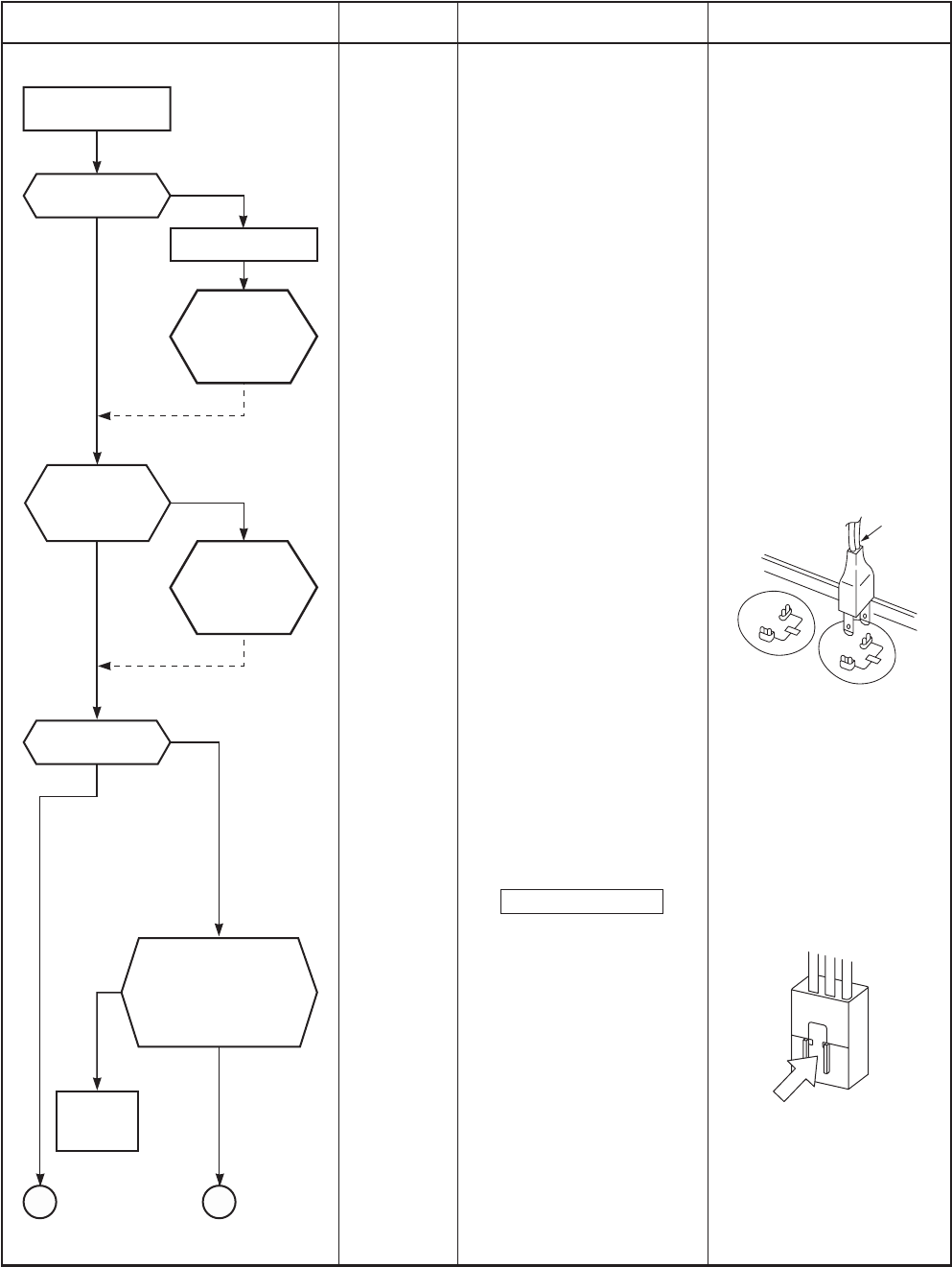
11-8-1. Summarized Inner Diagnosis of Inverter Assembly
Table 11-8-1
Replace
outdoor
fan motor.
Remove connector
of compressor.
NG
NG
NG
NO
OK
OK
OK
YES
Check 25A fuse
(Part No.F01).
Does outdoor
fan rotate?
Replace fuse.
Check
electrolytic
capacitor, diode
block (DB01),
etc.
Check
electrolytic
capacitor, diode
(DB01),
etc.
Remove connector
CN300 of outdoor fan
motor, and using a
tester, check resistance
value between every
phases at motor side.
Check
terminal voltage
of electrolytic
capacitor.
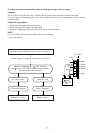
BA
Discharging position
(Discharging period
10 seconds or more)
Plug of
soldering
iron
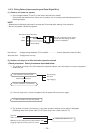
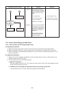
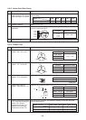
Diagnosis/Process flowchart Item
Preparation
Check
Check
Operation
Measure-
ment
Check
Stop
Check
Measure-
ment
Contents
Tu r n “OFF” the power supply
breaker, and remove 3P
connector which connects
inverter and compressor.
• Check whether 25A fuse
on the control board
assembly is blown or not.
(F01)
Turn on the power breaker,
and operate the air condi-
tioner in COOL mode by time
shortening.
Measure terminal voltage of
the electrolytic capacity.
500µF:400WV × 3
After operation, turn off the
power breaker after 2
minutes 20 seconds passed,
and discharge the electrolytic
capacitor by soldering iron.
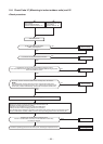
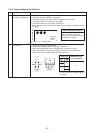
Check voltage between
motor phases.
• Is not winding between
-
‚
-
, or
-
opened
or short-circuited?
• Is not frame grounded with
,
, or
?
Summary
If fuse was blown, be sure to
check the electrolytic
capacitor and diode block.
(DB01)
• Connect discharge
resistance (approx. 100Ω,
40W) or soldering iron
(plug) between +, –
terminals of the electrolytic
capacitor (500µF) of C14
(with printed CAUTION
HIGH VOLTAGE) on P.C.
board.
OK if 500µF →
DC280 to 380V
Remove CN300 while
pushing the part indicated
by an arrow because CN300
is a connector with lock.
→ Resistance between
phases should be
approx. 55 to 77Ω
→ Should be 10MΩ or
more.