


NOTE: DIAGRAMS & ILLUSTRATIONS ARE NOT TO SCALE.
8
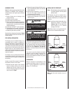
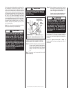
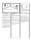
Figure 14
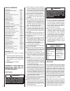
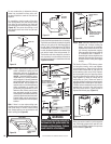
FRAMING WALL VARIATIONS
As many as six (6) different framed wall con-
figurations can be constructed to enclose the
Fireplaces. The following illustrations depict
these variations of wall enclosures. Several of
these designs may incorporate book shelves,
wood storage boxes, etc.
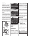
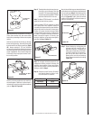
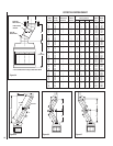
Figure 15
Framing Dimensions for Ceiling
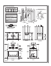
Figure 16
CST38MH - Wall Types
“C” Type Wall
“T” Type Wall
“L” Type Wall
“H” Type Wall
“Y” Type Wall
Parallel Wall
A
B
Ceiling Framing
C
D
Roof Framing
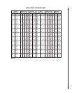
Framing Dimensions for Ceiling
Inches (millimeters)
Flue Type A B
FTF8, Vertical
at 2" (51 mm)
16 1/2"
(419 mm)
16 1/2"
(419 mm)
FTF8 Offset 30°
At 2" (51 mm)
16 1/2"
(419 mm)
27"
(686 mm)
Framing Dimensions for Roof
Inches
Pitch
FTF8 at 1" (USA)
C D*
0/12
16 1/2" 16 1/2"
6/12
16 1/2"
19"
12/12
16 1/2"
23 1/2"
* Perpendicular to roof ridge
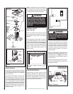
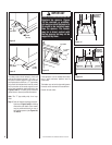
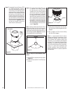
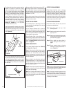
Step 4. The fireplace should be secured to side
framing members using nailing tabs. Use 8d
nails (Figure 17).
Nailing
Flange
Framing
Stud
Note: The nailing tabs are exempt from the
fireplace clearances described on the fireplace
clearance label.
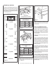
INSTALL THE COMBUSTION AIR KIT
(required in Manufactured Home installations)
Outside air drawn into the fireplace supplies
air to the fire for combustion. The outside air
kit (FOAK-6, Cat. No. 90L83) must be installed
before the fireplace is framed and enclosed in
the finished walls.
Install the air intake Collar (provided) as shown
in Figure 18.
There is a one-hand operated shut-off valve
located in the enclosed corner of the fireplace
opening behind the screen. Refer to label for
directions of operation. The combustion air
damper should be fully open when the fireplace
is in operation and fully closed when the fire-
place is not in use to prevent outside air from
entering your home.
Connect the 6” (152 mm) Class 0 or Class 1 air
duct to the outside air collar on the appliance
with the tie strip in the outside air kit (provided).
See Figure 18.
Route the Class 0 or Class 1 air duct out the
back or side wall, up through the ceiling or floor
joists to an outside wall. The air duct should be
located above snow level.
Outside combustion air may be run upwards
or vertically through framing and ceiling joists,
with the hood installed through an outside
wall and 3' (914 mm) below the termination.
Ducting may also be run downward through
floor joists and under the home to a ventilated
crawlspace not considered part of the living
area of the home.
Figure 17