


NOTE: DIAGRAMS & ILLUSTRATIONS ARE NOT TO SCALE.
11
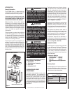
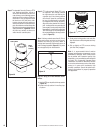
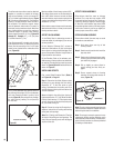
Step 5. The height of vertical chimney pipe sup-
ported only by the fireplace must not
exceed 30'. Chimney heights above 30'
must be supported by a Model FTF8-S4
stabilizer installed at 30' intervals.
Note: The Model FTF8-S4 adds 3" net effective
height to the total chimney system.
Install the Model FTF8-S4 stabilizer by fitting
inner section down into respective section of
proceeding flue pipe and locking outer stabilizer
section into place over the outer chimney pipe.
Position for proper clearance through framed
opening and nail straps securely (under tension
in “shear”) into place on framing. Use 8d nails.
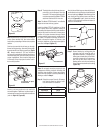
Attach successive lengths of chimney pipe
directly to stabilizer using same techniques as
described in Step 4 (Figure 27).
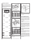
Locking Tabs
(Lances)
Note: Assemble one component of chimney at
a time (inner section first, then outer section
last) before proceeding with the next complete
section.
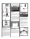
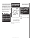
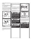
Continue to assemble the chimney up through
framed ceiling opening. Assemble just enough
to penetrate the roof flashing openings (Figure
26). Always maintain 2" (51 mm) minimum
air space to combustible materials and always
check each pipe joint (inner and outer) to ensure
proper engagement. Check vertical alignment
of chimney so that it projects from the roof in
true vertical position.
FTF8-S4 Stabilizer
2" (51mm) Min. Air Space
to Combustibles
Figure 26
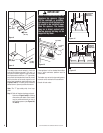
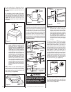
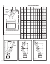
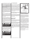
Step 7. Secure flashing by nailing along the
perimeter into roof using 8d nails or
equivalent fasteners. If shingled roof,
slide upper end and sides of roof flash-
ing under shingles (trim if necessary),
seal the top and both sides of the
flashing to the roof with roof caulking.
Cover fastener heads with roof caulking
(Figure 29).
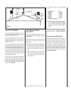
Figure 28
FTF8 Chimney
FTF8 Flashing
Do Not Seal
Figure 25
Figure 27
Note: Do not apply excessive pressure to any
subsequent chimney sections following the
stabilizer when installing. Ensure each subse-
quent chimney section is securely attached by
testing as noted in Step 4.
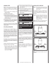
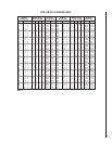
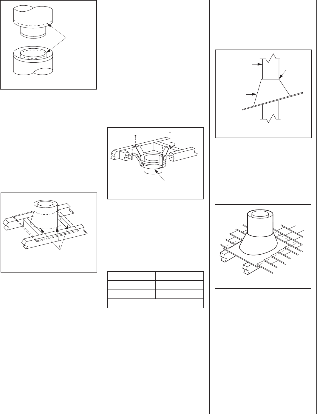
Step 6. Select the proper Security Chimneys
roof flashing based on pitch of roof.
Use chart below for selection:
Next, slide roof flashing over extended chimney
section that previously has been installed above
the roof opening in Step 4. Slide flashing all the
way down until the flashing base rests flat on
the roof (Figure 28). Again, check the vertical
position of the chimney and the minimum air
space to combustibles.
Roof Pitch FTF8
Flat to 6/12 F8-F6
6/12 to 12/12 F8-F12
Table 2
Figure 29
Security's chimney sections do not need to be
screwed together. Additional reinforcement is
not necessary except in certain offset conditions
(refer to Page 16, Figure 38).