


All installations and services must be performed by qualified service personnel.
24
1. Electrical Branch Supply Circuit
Route all electrical wiring to the left side of the furnace. The power supply circuit to the
furnace must be installed and grounded in accordance with the provisions of the National
Electrical Code, ANSI/NFPA-70-1999, or latest edition, and all local codes having
jurisdiction.
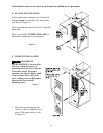
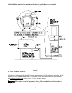
2. Connection Of Power Supply Wires
a. Remove the furnace control panel cover.
b. Insert 120 VAC wires through the strain relief bushing (or conduit connection as
applicable) on the left side of the furnace junction box.
c. Connect the “Hot” wire to the terminal block lug marked “L
1
”
.
d. Connect the “Neutral” wire to the terminal block lug marked “L
2
”.
e. Connect the “ground” wire to the terminal block lug marked “G”.
f. Reinstall and secure the control panel cover with the original mounting screws.
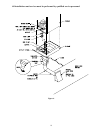
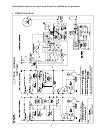
3. Connection Of Thermostat Wires
NOTE: Class 1 thermostat wire must be used inside the furnace burner compartment.
a. Insert 24 VAC wires through the plastic grommet on the left side of the furnace casing.
b. Connect the thermostat wires to the yellow leads from the burner (refer to the applicable
wiring diagram).
c. Connect the thermostat wires to the room thermostat.
IMPORTANT: The room thermostat should be installed 4 to 5 feet above the floor on
interior wall which is relatively free from direct sources of heat (sunlight or supply airflow)
or exposure to cold (drafts from open windows and doors). The nominal anticipator settings
are 0.8 amperes, for the GMC, and 0.2 amperes, for the OMC (refer to the thermostat
literature for additional information).
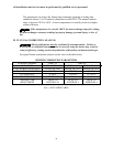
Five-conductor thermostat wire is recommended for 24 VAC, low-voltage, control circuit
wiring. Only 2 wires are required for the furnace (a heating application only).
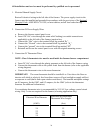
Electrical Wire Diameter
Maximum Recommended
Thermostat Wire Length
(AWG)
(feet)
24 55
22 90
20 140
18 225