


All installations and services must be performed by qualified service personnel.
13
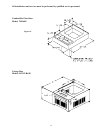
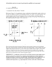
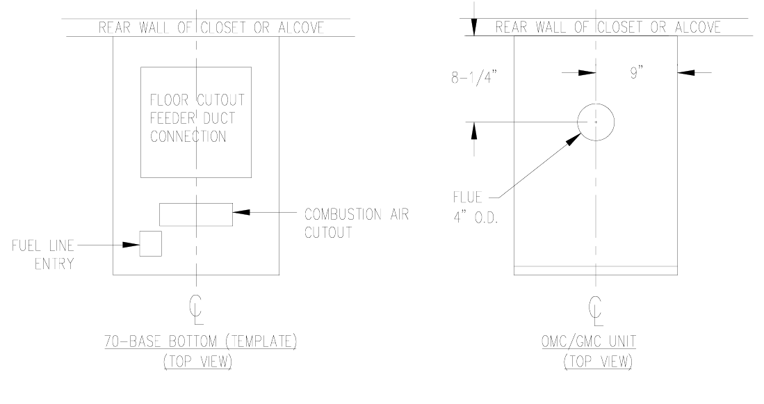
Figure 1B.
D. BASE INSTALLATION
1. Combustible Floor Base Model: 70-BASE
Referring to Figure 1A, for applications using a combustion air channel and a supply air duct, use
the base as a template to mark the floor opening locations. See Figure 2 for cutout locations. Cut
a square opening in the floor for the supply air duct. Cut the opening 1-inch larger than the
square template opening. Cut the combustion air duct opening. Cut opening 1/8 inch larger than
the template opening. See Figure 1A for cutout sizes.
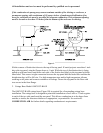
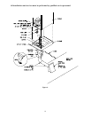
Figure 2.
Place the bottom base panel in position. Mark the square opening location on the distribution
duct at the connection point of feeder duct. Remove the bottom panel. Cut an opening in the duct
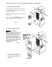
slightly larger than the feeder duct. Cut the feeder duct to length. (Refer to Figure 3 for location
of this cut.) Install the feeder duct. Bend over each tab. Insure an airtight seal by using high
temperature sealant or tape on the joint. Reinstall the bottom panel over the feeder duct. Insert
and secure the combustion air duct. Put the top panel in place.
IMPORTANT: A combustion air duct must be used. If the underside of the mobile home is
skirted or enclosed (e.g. enclosed in a crawlspace), the combustion air intake should exit
through the skirting, or enclosure, if at all possible. All joints and seams of supply ducts and
combustion air ducts must be closed with a sealing method suitable to the application
conditions and temperatures ( e.g. high temperature silicone caulk and/or aluminum tape).