


All installations and services must be performed by qualified service personnel.
3
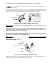
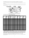
NOTE: ROTATION OF FLUE PIPE IS ONLY ALLOWED FOR LEFT HAND SIDE VENTING
APPLICATIONS.
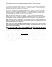
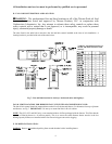
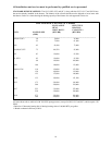
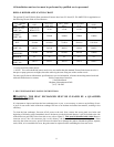
TABLE 1: Suggested sizes and positions of flue pipe opening on left hand side of casing.
TRIM COLLAR/
UNIT DIA. HOLE “X” DIM. “Y” DIM. FLUE DIA. GASKET PART #
OC2 5-1/2” 3-5/8” 28-3/8” 5” 14121/330073
OC5 6-1/2” 4-3/4” 31-7/16” 6” 14131/330005
OH2 5-1/2” 3/5/8” 28-3/8” 5” 14121/330073
OH3 6-1/2” 4-9/16” 32-3/16” 6” 14131/330005
OH5 6-1/2” 4-3/4” 33-1/16” 6” 14131/330005
OH11 6-1/2” 4-3/4” 35-1/4” 6” 14131/330005
OH16 7-1/2” 4-5/16” 41-3/8” 7” 14132/330006
OL2* 5-1/2” 3-5/8” 28-5/16” 5” 14121/330073
OL5* 6-1/2” 4-5/8” 34-15/16” 6” 14131/330005
OL11* 6-1/2” 4-1/2” 37-5/8” 6” 14131/330005
OL16* 7-1/2” 4-1/2” 39-1/8” 7” 14132/330006
OL20* 7-1/2” 4-1/2” 43-1/4” 7” 14132/330006
* FRONT FLUE MODELS ONLY
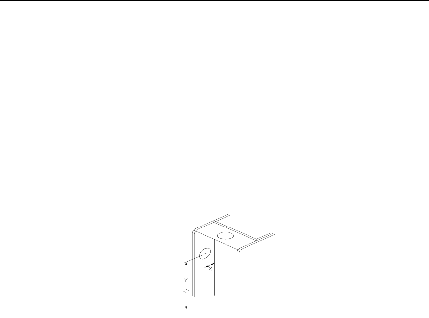
“X” DIMENSION IS MEASURED FROM SEPARATOR PANEL.
“Y” DIMENSION IS MEASURED FROM THE BLOWER PAN ON “H” MODELS AND FROM THE BASE ON
“L” AND “C” MODELS.
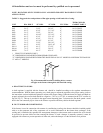
Fig 1: Recommended location for drilling hole to connect
vent pipe to the furnace through the left hand side casing.
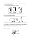
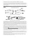
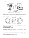
A. DRAFT REGULATORS:
A draft regulator is supplied with the furnace and should be installed according to the regulator manufacturers
recommendations. With the burner operating, use a draft gauge to adjust the regulator to the proper setting. (refer to
the instructions enclosed with draft regulator to adjust to the proper setting). When the burner air supply and draft are
properly adjusted, the overfire draft should be a negative (-).01" to (-).02" WC, as measured at the 5/16" overfire air
tap (See Fig. T). This tap is provided in the upper burner mounting plate. To measure the flue draft, punch a small
hole in the vent connector pipe as close to the furnace as possible and always before the draft regulator.
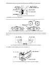
B. DUCT WORK/AIR CONDITIONING:
If the furnace is used in connection with summer air conditioning (cooling), the furnace should be installed parallel
with or on the upstream side of the evaporator coil to avoid condensation in the furnace heat exchanger. If the
cooling unit is installed with a parallel flow arrangement, dampers or other means used to control flow of air should
be provided to prevent chilled air from entering the furnace. If such a damper is manually operated, it must be
equipped with a means to prevent operation of either unit, unless the damper is in the full heat or cool position.