


All installations and services must be performed by qualified service personnel.
8
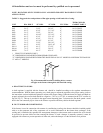
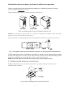
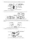
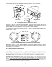
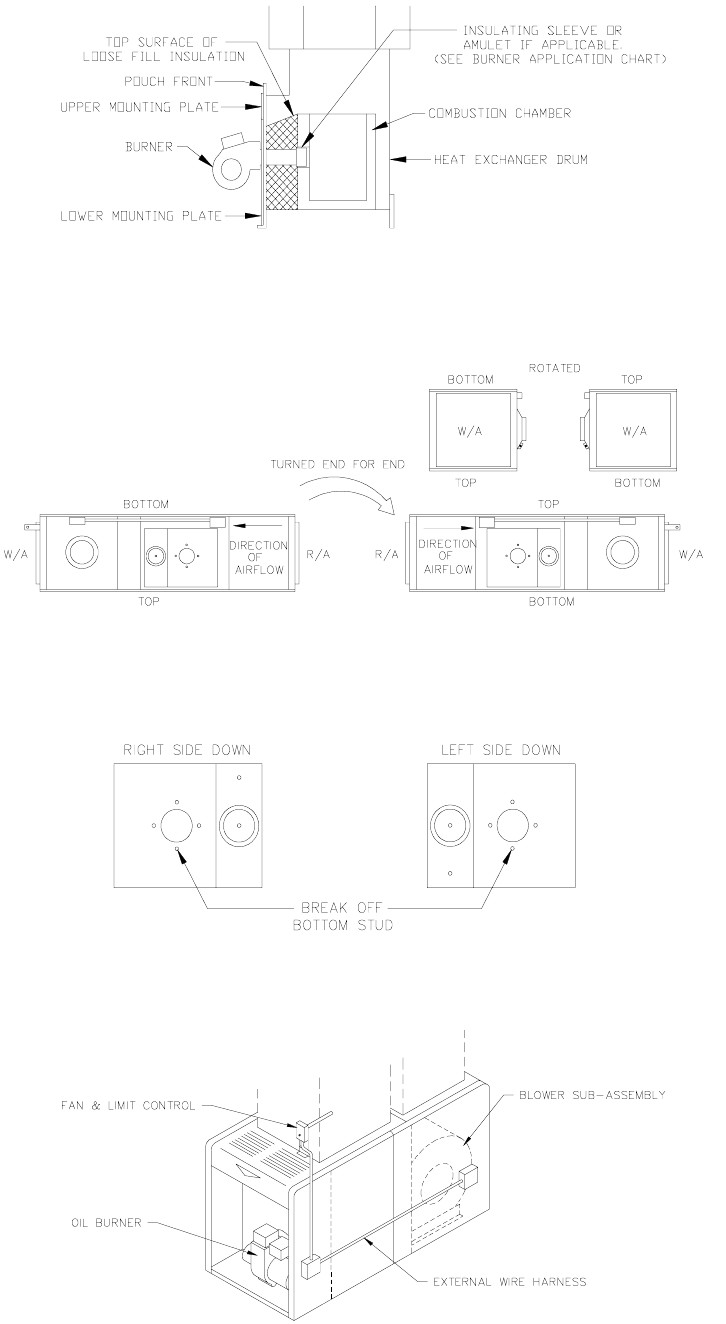
Fig. 10: (Side view) Burner insertion illustration
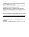
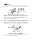
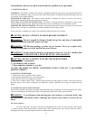
F. HORIZONTAL FURNACE POSITIONS:
The horizontal furnace may be turned end for end, or rotated, making the top into the bottom, as shown in Fig. 11.
Fig. 11: A horizontal furnace rotated 180° (or flipped end for end) to reverse airflow direction
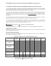
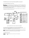
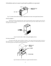
After the furnace has been positioned, the bottom burner mounting stud must be broken off before mounting the
burner (See Fig. 12). Also, the fan & limit and its mounting bracket must be relocated once the unit is in position.
(See Fig. 7).
Fig. 12: Required modification to burner mounting studs before burner installation
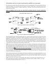
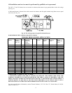
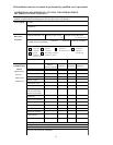
G. EXTERNAL WIRE HARNESS LOCATIONS FOR OL33, 37
Fig. 13: External electrical wiring in conduit on large furnace models