


All installations and services must be performed by qualified service personnel.
7
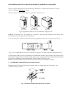
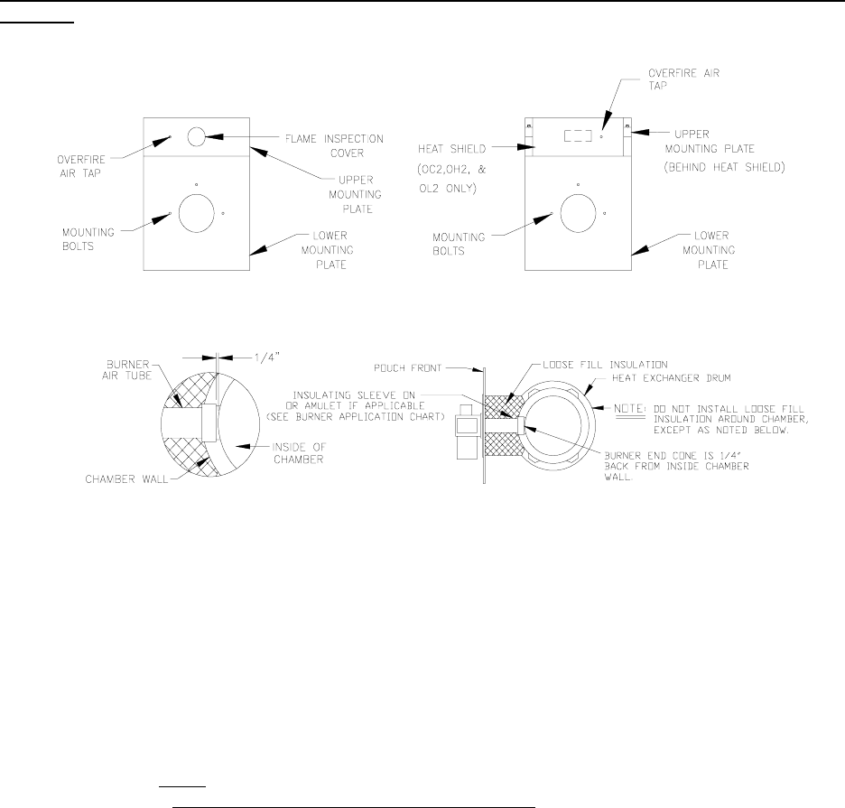
The oil burner will mount on three stud mounting bolts on the lower mounting plate covering the opening in the front
of the heat exchanger. The end of the burner tube should be inserted no further than 1/4 inch back from the inside
surface of the combustion chamber. A distance further than 1/4 inch back from the inside chamber wall may cause
impingement and sooting.
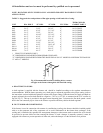
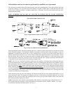
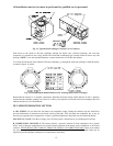
NOTE: OVERFIRE AIR TAP MAY BE LOCATED ON EITHER SIDE OF FLAME INSPECTION
COVER. (See Fig. 8).
TWO PIECE MOUNTING PLATE
Fig. 8: Typical location of the overfire air tap
Fig. 9: (Top view) Burner insertion illustration
When mounting the burner, the upper mounting plate (Fig. 8) must be removed to provide access to the area in front
of the combustion chamber. The combustion chamber can then be moved forward or backward slightly to allow for
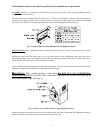
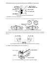
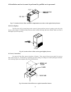
adjustment in positioning the burner tube. A fiber insulating sleeve or amulet is provided on the burner tube of
specific Thermo Pride burners.(see Fig. 10). See Thermo Pride burner application chart for type of insulator. Do not
allow the burner tube or end cone to physically touch or protrude into the chamber, as excess heat transfer could
result in destruction of the tube, end cone or both. The burner tube/end cone is properly positioned, when the end is
¼ inch back from the inside surface of the combustion chamber wall.
NOTE: The OL2, OC2 and OH2-56 furnace models have two chamber positioning clips on the pouch bottom to
prevent the chamber from being pulled forward too close to the mounting plate and burner. If the chamber is pulled
back against these clips the insertion depth should be correct. The loose-fill insulation that is included in a brown
paper bag should be lightly
placed around the burner tube between the front of the combustion chamber and the
burner mounting plate. (DO NOT PACK THE INSULATION DOWN).
The loose-fill insulation should be placed
in such a fashion that the surface of the insulation is sloped from the top of the combustion chamber to the top of the
lower mounting plate. The purpose of the loose insulation is to help protect the burner tube, mounting plates and
vestibule area from excessive temperatures.
On the horizontal units, the loose-fill insulation will fall down around the side of the chamber (the chamber is on its
side in horizontal units). This presents no problem to the unit, as the amount of insulation under the side will be
minimal, but take care not to allow the insulation to fall into the open end of the chamber where it may burn and
blow around, possibly lodging in the burner.
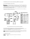
NOTE: Do not place loose insulation around chamber sides and back except for the larger units (Models OL33, 37
and 39) where the loose insulation is to be used around rear of chamber to ensure chamber stability. See larger
unit assembly instructions for further details. (See Fig. 9).